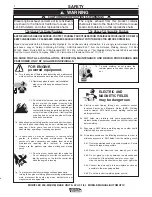
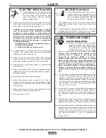
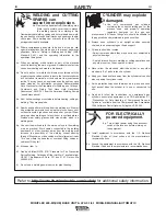
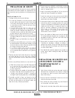
background image

FOR ELECTRICALLY
powered equipment.

8.a. Turn off input power using the disconnect

switch at the fuse box before working on
the equipment.

8.b. Install equipment in accordance with the U.S. National

Electrical Code, all local codes and the manufacturerʼs
recommendations.

8.c. Ground the equipment in accordance with the U.S. National

Electrical Code and the manufacturerʼs recommendations.

CYLINDER may explode
if damaged.

7.a. Use  only compressed gas cylinders

containing the correct shielding gas for the
process used and properly operating
regulators designed for the gas and

pressure used. All hoses, fittings, etc. should be suitable for
the application and maintained in good condition.

7.b. Always keep cylinders in an upright position securely

chained to an undercarriage or fixed support.

7.c. Cylinders should be located:

• Away from areas where they may be struck or subjected to

physical damage.

• A safe distance from arc welding or cutting operations and

any other source of heat, sparks, or flame.

7.d. Never allow the electrode, electrode holder or any other

electrically “hot” parts to touch a cylinder.

7.e. Keep your head and face away from the cylinder valve outlet

when opening the cylinder valve.

7.f. Valve protection caps should always be in place and hand

tight except when the cylinder is in use or connected for
use.

7.g. Read and follow the instructions on compressed gas

cylinders, associated equipment, and CGA publication P-l,
“Precautions for Safe Handling of Compressed Gases in
Cylinders,” available from the Compressed Gas Association
1235 Jefferson Davis Highway, Arlington, VA 22202.

WELDING and CUTTING
SPARKS can
cause fire or explosion.

6.a. Remove fire hazards from the welding area.

If this is not possible, cover them to prevent

the welding sparks from starting a fire.

Remember that welding sparks and hot materials from weld-
ing can easily go through small cracks and openings to adja-
cent areas. Avoid welding near hydraulic lines. Have a fire
extinguisher readily available.

6.b. Where compressed gases are to be used at the job site,

special precautions should be used to prevent hazardous
situations. Refer to “Safety in Welding and Cutting” (ANSI
Standard Z49.1) and the operating information for the
equipment being used.

6.c. When not welding, make certain no part of the electrode

circuit is touching the work or ground. Accidental contact can
cause overheating and create a fire hazard.

6.d. Do not heat, cut or weld tanks, drums or containers until the

proper steps have been taken to insure that such procedures
will not cause flammable or toxic vapors from substances
inside. They can cause an explosion even though they have
been “cleaned”. For information, purchase “Recommended
Safe Practices for the Preparation for Welding and Cutting of
Containers and Piping That Have Held Hazardous
Substances”, AWS F4.1 from the American Welding Society
(see address above).

6.e. Vent hollow castings or containers before heating, cutting or

welding. They may explode.

6.f. Sparks and spatter are thrown from the welding arc. Wear oil

free protective garments such as leather gloves, heavy shirt,
cuffless trousers, high shoes and a cap over your hair. Wear
ear plugs when welding out of position or in confined places.
Always wear safety glasses with side shields when in a
welding area.

6.g. Connect the work cable to the work as close to the welding

area as practical. Work cables connected to the building
framework or other locations away from the welding area
increase the possibility of the welding current passing
through lifting chains, crane cables or other alternate circuits.
This can create fire hazards or overheat lifting chains or
cables until they fail.

6.h. Also see item 1.c.

6.I. Read and follow NFPA 51B “ Standard for Fire Prevention

During Welding, Cutting and Other Hot Work”, available from
NFPA

1 Batterymarch Park, PO box 9101, Quincy, Ma

022690-9101.

6.j. Do not use a welding power source for pipe thawing.

iii

SAFETY

iii

Refer to 

http://www.lincolnelectric.com/safety

for additional safety information.

MOBIFLEX 400-MS(/HE) BASE UNIT & LFA 3.1/4.1 MOBILE MANUAL/AUTOMATIC

Summary of Contents for LFA 3.1

Page 1: ...11 Safety Depends on You Lincoln arc welding and cutting equipment is designed and built with safety in mind However your overall safety can be increased by proper installation and thoughtful operatio...

Page 2: ...THEIR DOCTOR BEFORE OPERATING Read and understand the following safety highlights For additional safety information it is strongly recommended that you purchase a copy of Safety in Welding Cutting AN...

Page 3: ...rically hot parts of electrode holders connected to two welders because voltage between the two can be the total of the open circuit voltage of both welders 3 i When working above floor level use a sa...

Page 4: ...c lines Have a fire extinguisher readily available 6 b Where compressed gases are to be used at the job site special precautions should be used to prevent hazardous situations Refer to Safety in Weldi...

Page 5: ...laitier en fusion sont mises de l arc de soudage Se prot ger avec des v tements de protection libres de l huile tels que les gants en cuir chemise paisse pan talons sans revers et chaussures montantes...

Page 6: ...correct replacement parts On Line Product Registration Register your machine with Lincoln Electric either via fax or over the Internet For faxing Complete the form on the back of the warranty statemen...

Page 7: ...Description B 2 Product Combinations B 3 Operation B 3 Automatic Filter Cleaning System B 5 Off line Cleaning B 6 Filter Replacement B 7 Emptying The Dust Tray B 8 Accessories Section C Options C 1 K1...

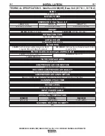
Page 8: ...PTION Max 2 1 SCFM 60 nl min depending on the degree of saturation of the filter CLEANING CYCLE TIME 60 min SOUND LEVEL 69 db A According to ISO 3746 INPUT POWER CABLE 20 ft 6 m MAXIMUM RELATIVE HUMID...

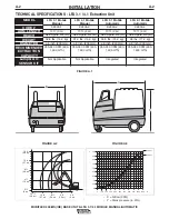
Page 9: ...kg 37 3 lbs 16 9 kg 33 5 lbs 15 2 kg 38 lbs 17 2 kg DIAMETER 8 inch 203 mm 8 inch 203 mm 8 inch 203 mm 8 inch 203 mm RECOMMENDED EXTRACTION CAPACITY 355 940 CFM 600 1 600 m3 h 355 940 CFM 600 1 600 m3...

Page 10: ...d filtering fume which is released during the most common welding processes such as MIG MAG solid wire GMAW MIG MAG flux cored wire FCAW TIG GTAW welding Stick welding MMA or SMAW Autogeneous welding...

Page 11: ...akes reposi tioning the arms simple easy and effortless The extraction arms are made of solid lightweight 8 inch 203 mm diameter dent and scratch resistant tubes They are provided with a spring balanc...

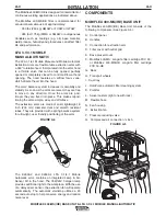
Page 12: ...8 2 Washer If parts are missing or damaged contact Lincoln Electric Automation 888 935 3878 INSTALLATION MOBIFLEX 400 MS HE BASE UNIT The base swivel mount on top of the machine contains two tie wraps...

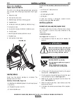
Page 13: ...t the red plastic ring 12 Fold back the rubber seal and place it over the hose The underside of the rubber seal should cover the red plastic ring 0 5 1 inch LFA 3 1 4 1 MOBILE MANUAL The supply cable...

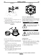
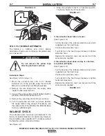
Page 14: ...balanced in the factory for optimal balance and positioning However they sometimes need adjustment To check and adjust the balance system proceed as follows See Figure A 11 1 Bring the extraction hood...

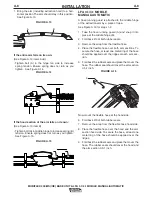
Page 15: ...6 for steps 1 9 1 Take the hose running guard A and snap it into place at the middle hinge B 2 Fold back 2 3 of both rubber seals 3 Remove the wrap from the flexible hose 4 Place the flexible hose ove...

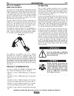
Page 16: ...outside The operation of welding fume control equipment is affected by various factors including proper use and positioning of the equipment maintenance of the equipment and the specific welding proc...

Page 17: ...FCAW TIG GTAW welding Stick welding MMA or SMAW Autogeneous welding The Mobiflex 400 MS is designed for intermittent or continuous welding applications as indicated above The Mobiflex 400 MS filter is...

Page 18: ...on arm with integrated Lamp Arc Sensor Kit K1668 3 1 Hose and Hood Set instead of extraction arm OPERATION The air which contains welding fume is captured extracted and filtered before being recircula...

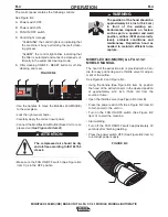
Page 19: ...f the airflow See Figure B 2 and Figure B 3 Using the handle See Figure B 3 item A position the hood of the extraction arm in the desired position at approximately 6 12 inch 15 30 cm from the source o...

Page 20: ...the on off switch See Figure B 4 item D Start welding Turn off the machine approximately 20 seconds after finishing welding using the on off switch See Figure B 4 item D Press the power switch OFF Se...

Page 21: ...proceed as fol lows Make sure the FAN ON OFF switch See Figure B 2 item C is off Close throttle valve in extraction hood Press filter cleaning ON OFF RESET button See Figure B 2 item E to start off li...

Page 22: ...he previously removed parts in reverse order PREFILTER Replace the prefilter See Figure B 6 item B When it is clogged or saturated and cannot be cleaned using a vacuum cleaner or When it has been dama...

Page 23: ...f the machine 2 Carefully take out the dust tray A The dust tray can be emptied in different ways Using an industrial vacuum cleaner preferred way or Empty in a plastic bag 3 Empty the dust tray In ca...

Page 24: ...C 1 ACCESSORIES C 1 OPTIONS K1668 3 HOSE AND HOOD SET OPTION The Mobiflex 400 MS HE Base Unit can be equipped with a Hose and Hood Set instead of a flexible extrac tion arm...

Page 25: ...are required which are described in this chapter Maintenance intervals can vary depending on the spe cific working conditions such as ambient conditions welding consumables and process es base materi...

Page 26: ...ng Section X Clean with an industrial vacuum cleaner that meets OSHA guidelines for Cr6 housekeeping X EVERY MONTH EVERY 6 MONTHS EVERY 12 MONTHS TABLE D 2 PERIODIC MAINTENANCE LFA 3 1 4 1 MOBILE AUTO...

Page 27: ...DISPOSAL After life of the product dispose of product in accor dance with federal state or local regulations MOBIFLEX 400 MS HE BASE UNIT LFA 3 1 4 1 MOBILE MANUAL AUTOMATIC FIGURE D 1 C F A C B B 36...

Page 28: ...bute to the machine symptom Step 3 RECOMMENDED COURSE OF ACTION This column provides a course of action for the Possible Cause generally it states to contact your local Lincoln Authorized Field Servic...

Page 29: ...tive Replace pressure difference switch No compressed air or compressed air pressure too low Check compressed air system and or compressed air connection Motor protection switch defective Replace the...

Page 30: ...ee Prefilter the pre filter Outside air is being extracted Check or replace the sealing mate rial Outlet grid blocked Remove obstructions from the out let grid Extraction fan polluted Clean the extrac...

Page 31: ...s safely contact your Local Lincoln Authorized Field Service Facility for technical troubleshooting assistance before you proceed CAUTION MOBIFLEX 400 MS HE BASE UNIT LFA 3 1 4 1 MOBILE AUTOMATIC ONLY...

Page 32: ...much friction Adjust friction See Balance Check Extraction capacity insufficient Pollution of the facility Throttle valve closed Open throttle valve Flexible hose s torn or loose Replace flexible hose...

Page 33: ...eference only It may not be accurate for all machines covered by this manual The specific diagram for a particular code is pasted inside the machine on one of the enclosure panels If the diagram is il...

Page 34: ...NOTES MOBIFLEX 400 MS HE BASE UNIT LFA 3 1 4 1 MOBILE MANUAL AUTOMATIC...

Page 35: ...NOTES MOBIFLEX 400 MS HE BASE UNIT LFA 3 1 4 1 MOBILE MANUAL AUTOMATIC...

Page 36: ...d Entl ftung des Arbeitsplatzes G Mantenha seu rosto da fuma a G Use ventila o e exhaust o para remover fumo da zona respirat ria G Turn power off before servicing G Desconectar el cable de ali mentac...

Page 37: ...parts or electrode with skin or wet clothing G Insulate yourself from work and ground G No toque las partes o los electrodos bajo carga con la piel o ropa moja da G Aislese del trabajo y de la tierra...

Page 38: ...and Service through Subsidiaries and Distributors Worldwide Cleveland Ohio 44117 1199 U S A TEL 888 935 3878 FAX 216 383 8823 WEB SITE www lincolnelectric com World s Leader in Welding and Cutting Pr...

Reviews: