B-4
OPERATION
B-4
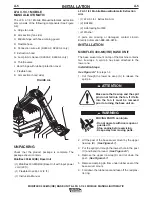
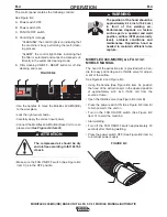
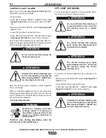
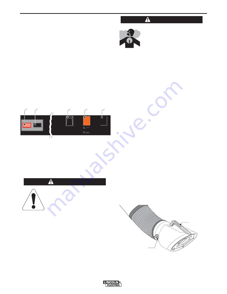
The control panel contains the following controls:
See Figure B.2
A. Power switch OFF
B. Power switch ON
C. FAN ON/OFF switch
D. Control light (orange)
- “CLEANING”: the control light is on indicating that
the machine is busy performing the (self-)clean-
ing process.
- “ALARM”: the control light blinks indicating that
the filter is saturated and cannot be cleaned suf-
ficiently in the automatic cleaning mode.
E. Filter cleaning ON/OFF - RESET button for off-line
cleaning and reset.
• Use the handles to move the Mobiflex 400-MS(/HE)
to the workplace.
• Lock the right swivel caster.
• Carefully apply the correct input power.
• Connect the Mobiflex 400-MS(/HE) Base Unit to com-
pressed air (
See Figure A.5 item Q
).
• Make sure the FAN ON/OFF switch (See Figure B.2
item C) is in the OFF position.
MOBIFLEX 400-MS(/HE) & LFA 3.1/4.1
MOBILE MANUAL
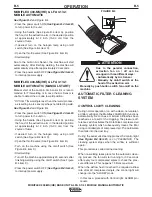
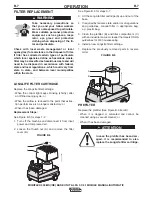
The hood of the extraction arm is provided with a han-
dle for easy positioning and a throttle valve for adjust-
ment of the airflow.
See Figure B.2 and Figure B.3
• Using the handle (See Figure B.3 item A), position
the hood of the extraction arm in the desired position
at approximately 6-12 inch (15-30 cm) from the
source of fume.
• Open the throttle valve (See Figure B.3 item B).
• Press the power switch ON (See Figure B.2 item B)
to turn power to the unit on.
• Turn on the FAN ON/OFF switch (See Figure B.2
item C) to start the machine.
• Start welding.
• Turn off the FAN ON/OFF switch approximately 20
seconds after finishing welding.
• Press the power switch OFF (See Figure B.2 item A)
to interrupt power supply.
MOBIFLEX 400-MS(/HE) BASE UNIT & LFA 3.1/4.1 MOBILE MANUAL/AUTOMATIC
FIGURE B.2
f
f
o
/
n
o
g
n
i
n
a
e
l
c
f
f
o
/
n
o
n
a
f
reset
cleaning
alarm
1
0
A
B
C
D
E
The compressed air should be dry
and oil-free according to ISO 8573-3
class 6.
------------------------------------------------------------------------
ATTENTION
The position of the hood should be
approximately 6-12 inch (15-30 cm)
in front of the welding arc.
Performance depends on factors
such as part vs. operator and weld
position, airflow (CFM and velocity
level), ambient conditions and
maintenance. Reposition hood as
needed to maintain efficient fume
capture.
------------------------------------------------------------------------
WARNING
FIGURE B.3
B
A

