background image


Dear Customer


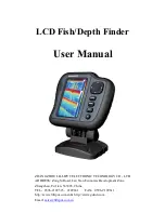
Thank  you  for  choosing  Lilliput’s  LCD  fish  finder.  This  product  adopts 

high-performance  embedded  computer  hardware.  It  is  designed  for  operations  under 

relatively  harsh  marine  environments  and  featuring  water  prove,  damp  prove, 

corruption  protection,  wide  voltage  range  protection  etc.  The  delicately  optimized 

design meets the requirements of all users in its applications to various conditions and 

occasions. Lilliput aims to server our customer with its excellent quality and exquisite 

manufacturing technology. 

We encourage you to read this installation and operations carefully in order to get full 

benefit from all the features and application of this product.   

Notice


Do not power on the equipment when the transducer is expose to the air. It might 
cause the damage to the transducer. 


Install the transducer according to the instruction. Do not bend, twist, pull or press 
the cable of the transducer. 


The  extension  cable  needs  to  put  inside  the  seal  terminal  box.  The  cable  of  the 
transducer is not allowed to touch the surface of the boat.   


Once the equipment’s power has been put into the “on” position do not switch the 
computer’s power


to the “off” position until the computer is fully booted. 


Please make sure that the power voltage setting has been adjusted to the standard 

voltage value of the location where the product is being used. 


Before using this product, please first make sure that all external wires and power 

adapters have been correctly connected. If you suspect any defects, please contact 

your sales agent or factory personnel immediately. 


Dust, humidity and dramatic temperature changes will affect the usage life of this 

computer. Please keep the machine away from these hazards.   


In  cleaning  the  units  do  not  use  chemical  detergents.  Remove  dust  with  a  soft 
cloth to ensure brightness. 

 
Warnings


High  Voltage  Circuit!  Disassembly  and  repair  of  device  should  only  be 
performed by authorized service personal. 
 
Power off the device from the plane immediately if there is water leaking into 
the  equipment.  Continuous  using  the  equipment  might  causes  short  circuit. 

Please contact our service under those circumstances.   


Do not attempt to modify or repair the original equipment. It may cause the 
damage of the precious electronic components inside the device. 


Power  off  the  device  from  the  plane  immediately  if  there  is  fire  or  smoke 
around.  Continuous  using  the  equipment  might  causes  short  circuit.  Please 

contact our service under those circumstances 

Summary of Contents for LCD Fish/Depth Finder

Page 1: ...OU LILLIPUT ELECTRONIC TECHNOLOGY CO LTD ADDRESS Zong Si Road Lan Tian Economic Development Zone Zhangzhou Fu Jian 363005 China TEL 0596 2109323 2109661 FAX 0596 2109611 http www lilliput com cn http...

Page 2: ...computer s power to the off position until the computer is fully booted Please make sure that the power voltage setting has been adjusted to the standard voltage value of the location where the produc...

Page 3: ...3 4 Transducer Installation 6 3 5 Device Cable Interfaces 8 4 Display Windows 9 4 1 Title Screen 9 4 2 Sonar View 9 4 3 Sonar Zoom View 11 4 4 Dual Sonar View 12 4 5 Big Digital View 13 4 6 Circular...

Page 4: ...range up and down range User to adjust the screen split ratio Data recording and playback High sensitivity gain and the gain in shallow water clear bottom echo detection Multiple alarm modes depth vol...

Page 5: ...5 Background colors white blue black 16 Output power 300W 17 Power supply DC 8 5V 24V 18 Working Environment 0 to 50 relative humidity below 95 19 Storage Temperature 20 70 20 Degree of protection IP6...

Page 6: ...5 3 2 Whole Device Installation...

Page 7: ...g location is very important and will affect the measure accuracy of the transducer directly It is recommended to install it on the bilge where the surface is smooth and flat Keep the transducer far a...

Page 8: ...does not tilt 2 Holding the transducer bracket template for the boat to mark the two mounting holes Center of two holes should be parallel to the surface Ensure that the bottom of the template and the...

Page 9: ...8 3 5 Device Cable Interfaces...

Page 10: ...When the sonar signal bounces between the bottom and the surface of the water and back again Use the appearance of the second return to determine bottom hardness Hard bottoms will show a strong secon...

Page 11: ...white line User set according to personal habits default value white lines 16 Cursor measurements the screen does not pop up in any menu press the four arrow keys in the left right measure Measurement...

Page 12: ...nce back again between the bottom and the bottom surface use of the second return appearance to determine the hardness of the bottom hard bottom will show the first sonar return stronger than the seco...

Page 13: ...tom and the bottom surface use of the second return appearance to determine the hardness of the bottom hard bottom will show the first sonar return stronger than the second one and soft bottom will di...

Page 14: ...ay the current location of underwater transducer temperature the current water temperature alarm can be set set off according to user needs or display default value off 4 Water surface noise often ref...

Page 15: ...nce to determine the hardness of the bottom hard bottom will show the first sonar return stronger than the second one and soft bottom will display the first sonar return weaker than the second one d T...

Page 16: ...o access the menu system Boot Options menu to view each option in the menu In the boot LOGO if you press the MENU button then the host will start the simulation system In the rest of the system screen...

Page 17: ...as unit 0 to 397 levels step size is 1 and the minimum interval with lower range is 3m B feet as unit 0 to 1302 levels step size is 1 and the minimum interval with lower range is 10 feet C fathom as u...

Page 18: ...ctive immediately long keep press to make step size adjustment effective after release This feature shows location on the screen The upper depth alarm is less than lower depth alarm and different dept...

Page 19: ...ty the more precise data for judge to determine the more detailed data Value default as 5 5 Real time Window Off Standard Wave this feature shows the real times of current sonar return Users can set v...

Page 20: ...gnals When the Voltage Alarm is on the voltage display window will flash in red characters if the current input voltage value is less than the voltage alarm value 8 Language Chinese English default as...

Page 21: ...tcut key to pop up shortcut menu and then adjust the brightness through the left and right keys of Four in one multi function key It s effective immediately through short press and long keep press 2 B...

Page 22: ...View Sonar Zoom View Double Sonar View Big Digit View Circular View Version Information Simulation Depth excursion 5m Shallow water alarm 0 4 30m Depth alarm Upper depth 1 50m Lower depth 2 400m Low v...

Page 23: ...2MM 8 pcs 10 Jack import slot 1 pcs 3 Jack import slot screws KB3 9 2 pcs 11 Device base 1 pcs 4 Line holder screws KB2 3 6 2 pcs 12 Probe line holder 1 pcs 5 Probe rotation axis 1 pcs 13 Hull over th...

Reviews: