background image


6. Software Control - Using Lightware Device Controller 

MODEX-F15-OPTS, MODEX-F15-OPTM series – User's Manual 

35

The Layout of the Crosspoint Menu

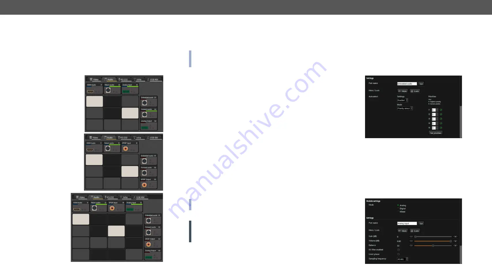
The  analog/digital  ports  are  displayed  in  the  crosspoint  menu 

depending on the selected mode. In Analog mode the digital input and 

output ports are hidden. In Digital mode the analog ports are hidden. 

In Mixed mode both analog and digital ports are displayed but the 

available crosspoint possibilities are limited, see the details in 

Mixed 

Audio Mode

 section.

See the differences in the available crosspoint settings:

Analog mode

Digital mode

Mixed mode

6.5.1. 

Port Properties - Transmitter

Click  on  the  desired  input/output  port  to  open  the  port  properties 

window. This section shows the available settings on the various port 

types.

INFO: The listed input and output port types and the available 

settings may be different in your device. The available port types 

depend on the installed video and interface modules.

Input ports:


HDMI audio

: the original embedded digital audio coming from the 

HDMI input port.


DP audio

: the original embedded digital audio coming from the 

DisplayPort input port.


Return audio

: digital audio transmitted by the receiver via the 

optical line.


S/PDIF input

: digital audio received on the S/PDIF input port.


Analog input

: analog audio received on the 5-pole Phoenix input 

port.

Output port:


Embedded audio

: the original embedded digital audio coming 

from the HDMI / DVI-D / DP input ports and transmitted to the 

receiver via the optical line.


Forward audio

: the audio line coming from the HDMI / DVI-D / 

DP input ports, the S/PDIF or the analog audio input port and 

transmitted via the optical line.


S/PDIF output

: digital audio which is transmitted over the S/PDIF 

output port.


Analog output

: analog audio which is transmitted over the 5-pole 

Phoenix output port.

INFO: The embedded audio and the forward audio are independent 

signals in the fiber optical lines and they can be transmitted together.

Audio Settings

ATTENTION!

 The following section lists all available settings but 

they cannot be applied to all ports. The available options depend on 

the type of audio port and the installed video and interface Modules 

in your recent MODEX device.


Change the name of the port;


Mute/Unmute the port;


Lock/Unlock the port;


Audio mode: Analog / Digital / Mixed;


Autoselect settings - see the details below;


Analog audio settings - see the details below;


Factory default settings.

Autoselect Mode and Settings

Autoselect mode is available on the output ports. Input port selection 

can be managed automatically by enabling this function. See more 

details about it in 

The Autoselect Feature

 section.

Analog Audio Settings - Input

The input analog audio settings are available by clicking on the Analog 

Input port. The following options can be set:


Gain (dB);


Volume (dB);


Balance (dB);


DC filter enable / disable (the factory default value is disabled);


Invert phase enable / disable (the factory default value is disabled);


Sample frequency (the factory default value is 48 kHz).

 

Summary of Contents for MODEX-F15-OPTM-RX

Page 1: ...MODEX F15 OPTS TX MODEX F15 OPTM TX MODEX F15 OPTS RX MODEX F15 OPTM RX User s Manual Modular Fiber Optical Multimedia Extender ...

Page 2: ...o the floor wall or mount in accordance with the installation instructions The apparatus shall not be exposed to dripping or splashing and that no objects filled with liquids such as vases shall be placed on the apparatus No naked flame sources such as lighted candles should be placed on the apparatus CAUTION AVIS RISK OF ELECTRIC SHOCK DO NOT OPEN RISQUE DE CHOC ELECTRIQUE NE PAS OUVRIR Waste Ele...

Page 3: ...yet but can be useful Navigation Buttons Go back to the previous page If you clicked on a link previously you can go back to the source page by clicking the button Navigate to the Table of Contents Step back one page Step forward to the next page Document Information Allpresentedfunctionsrefertotheindicatedproducts Thedescriptions have been made during testing these functions in accordance with th...

Page 4: ...sspoint Settings Menu 25 4 6 Port Status Settings Menu 25 4 6 1 Video Ports 25 4 6 2 Audio Ports 26 4 6 3 Serial Ports 26 4 6 4 IR Ports 27 4 6 5 USB K M Ports 27 4 6 6 Ethernet Port 27 4 7 EDID Settings Menu 27 4 7 1 EDID Switch in Transmitter 27 4 7 2 EDID Switch in the Receiver 27 4 7 3 EDID View in the Transmitter and Receiver 28 4 8 Network Settings Menu 28 4 8 1 DHCP 28 4 8 2 Static IP Addre...

Page 5: ...nput 64 7 7 11 Mute Audio Output 64 7 7 12 Unmute Audio Output 64 7 7 13 Analog Audio Input Level Settings 64 7 7 14 Analog Audio Output Level Settings 65 7 8 Network Configuration 66 7 8 1 Query the DHCP State 66 7 8 2 Change the DHCP State 66 7 8 3 Query the IP Address 66 7 8 4 Change the IP Address Static 66 7 8 5 Query the Subnet Mask 66 7 8 6 Change the Subnet Mask Static 66 7 8 7 Query the G...

Page 6: ...sed by long cables or connector reflections Variable A V Modules MODEX can be supplied with different type of Video ports both on transmitter and receiver side HDMI DVI DisplayPort and 3G SDI connectors To increase the flexibility transmitter and receiver can be assembled with different type of video ports MODEX F15 OPTS TX Transmitter Receiver Model number Modular extender Optical interface singl...

Page 7: ...lifier Speakers DVI Display Keyboard Mouse DP Touch control Mac DP Ethernet Projector DVI DL RS 232 Speakers HDMI Blu ray player Touch control RS 232 IR IR emitter DVI Display Projector DVI Ethernet PC HDMI Laptop DVI Touch control RS 232 MacBook 25G Hybrid Frame CONTROL ROOM MODEX receiver ENTER ESC CPU LIVE 5V 3 3V ETHERNET 10 100 AUDIO VIDEO OPTS LINK RESET MODEX F15 OPTM RX 111 DETECT TX MEX 1...

Page 8: ...lso the mounting options and further assembly steps 2 1 Mounting Options Devices can be mounted in several ways depending on the application Besides using with rack shelf a mounting bracket is available which offers easy mounting on truss systems with standard clamps The bracket can be also used for building the unit into the furniture ATTENTION Pay attention to the ventilation holes when designin...

Page 9: ...n to the AC power socket Touch panel Ethernet Audio amplifier MODEX receiver MODEX transmitter Power Projector Media player Keyboard Mouse Transmitter side Receiver side IR LAN RS 232 Power OPTS OPTM Audio HDMI DVI DP RS 232 Power Power Remote controller IR USB PC HDMI DVI DP USB Infrared Audio OPTM OPTS Receiver Connect a multi OPTM or single mode OPTS fiber cable to channel B of the receiver HDM...

Page 10: ...he OPTM designation and the part number 1 USB KVM USB connection to HOST Computer unit via USB B type connector See more information about USB KVM function in USB Interface KVM Function section 2 Ethernet Locking RJ45 socket Remote control port for connecting the unit to Local Area Network LAN 3 Signal Status LEDs Audio LED lights green when the audio transfer is active Video LED indicates correct...

Page 11: ...operation on the LCD with 2x16 characters See more information about menu control in Front Panel Menu Concept section 5 Menu navigation Up down left right enter and escape buttons for menu navigation See more information about menu control in Front Panel Menu Concept section 6 CPU and PSU Status LEDs CPU live LED blinks to indicate normal operation 5V and 3 3V LEDs light green when the extender is...

Page 12: ...C power Power connector IEC power Power connector Neutrik NAC3MPA 1 Fiber type Single mode Fiber type Multi mode Fiber type Single mode Extension distance 10000m Extension distance 300m Extension distance 10000m Module code MODEX CON OPTM NT PCN Module code MODEX CON OPTS HF4 Module code MODEX CON OPTM HF4 Part nr 9161 0232 Part nr 9161 0233 Part nr 9161 0234 Connector type Neutrik OpticalCON DUO ...

Page 13: ...ud rate from 4800 to 460800 Baud rate from 4800 to 460800 Baud rate from 4800 to 460800 No longer available discounted module Module code MODEX IF RS232 IR Module code MODEX IF ETH Module code MODEX IF AUDIN Part nr 9161 0715 Part nr 9161 0718 Part nr 9161 0719 Connector type 2x3 5 mm TRS connector 1 8 mini jack Connector type RJ45 female Connector type RCA I O frequencies 38 kHz 38 kHz Ethernet d...

Page 14: ...EX AV HDMI DVI 4K IM Part nr 9161 0401 Part nr 9161 0407 Part nr 9161 0410 Connector type DVI D receptacle Connector type DVI D receptacle Connector type DVI D receptacle Supp video formats DVI 1 0 Supp video formats DVI 1 0 Supp video formats DVI 1 0 Max resolution 2560x1600 60Hz 1920x1200 120Hz Connector type HDMI receptacle Connector type HDMI receptacle Max pixel clock 165 MHz Supp video forma...

Page 15: ...Hz 1920x1080p 120Hz Max pixel clock 165 MHz Max pixel clock 225 MHz Max pixel clock 225 MHz Embedded audio No Embedded audio Yes Embedded audio Yes Return audio No Return audio No Return audio No No longer available discounted module Module code MODEX AV DP OM Module code MODEX AV DVI OM Module code MODEX AV DVI 4K OM Part nr 9161 0422 Part nr 9161 0430 Part nr 9161 0436 Connector type Standard Di...

Page 16: ...ink signal is to be sent use only dual link capable DVI cables 3 6 3 DisplayPort Connector CertainvideoModulesofMODEXtransmitterandreceiver provide standard 20 pole DisplayPort connectors for inputs and outputs Always use high quality DP cable for connecting sources and displays 3 6 4 BNC Connectors Standard BNC receptacle is used for SD HD 3G SDI input and outputs Recommended coax cable type Beld...

Page 17: ...nector MODEX extenders provide USB connectors for supporting KVM functionality The transmitter has 1x USB 2 0 B type connector and the receiver has 2x USB 2 0 A type connectors You can find more information about USB KVM function in in USB Interface KVM Function section 3 6 11 Fiber Optical Connectors MODEX can be ordered with various types of standard fiber optical connectors ST receptacle SC rec...

Page 18: ... cable extension distances supported can be found in Maximum Fiber Cable Extensions section Analog Digital audio Ethernet RS 232 RS 422 Infrared USB INPUT OPTS OPTM OUTPUT HDMI DVI D DP Analog Digital audio Ethernet RS 232 RS 422 Infrared HDMI Analog Digital audio Ethernet RS 232 RS 422 Infrared USB INPUT OPTS OPTM OUTPUT HDMI DVI D DP Analog Digital audio Ethernet RS 232 RS 422 Infrared 3 9 Audio...

Page 19: ...audio signal from the Media player is transmitted to the analog sink device Audio amplifier through the fiber optical line Digital audio signal from the Blu ray player is transmitted to the analog sink device Audio amplifier and analog audio signal from the Media player is transmitted to the digital sink device HD TV MODEX transmitter Blu ray player FIBER OPTICAL HDMI IN HDMI OUT AUDIO IN MODEX re...

Page 20: ...ws First detect mode selected input port is kept connected to the output while it has an active signal Priority detect mode always the highest priority active input is selected to transmit Last detect mode always the last attached input is selected to transmit INFO The input ports where the priority is set to 31 will not be scanned Flowchart of Autoselection Modes Automatic Input Selection Example...

Page 21: ...re enumeration of the USB device Composite Mode The composite mode is an advanced data transmission method recommended for most users MODEX devices use their own data packets during data transmission Thus the content of the transmitted packets is known to the Lightware infrastructure Key Features Supports the following HID compliant devices computer mouse keyboard built with at most 107 keys and o...

Page 22: ...Injection 2 Loopback 3 Extended data Transmitter RX data TX data RS 232 TCP converter Receiver TX data RX data RS 232 TCP converter 1 2 2 3 1 3 Fiber cable INFO You can find the related settings for Lightware Device Controller software in RS 232 Layer section 3 13 2 Infrared Interface Technical Background All infrared input data are transmitted to the remote device all the time Thus the link does ...

Page 23: ...ns The EDID memory consists of four parts Factory EDID list shows the pre programmed EDIDs F1 F136 Dynamic EDID list shows the display device connected to the outputs of the device The unit stores EDID of the last device connected to an output so there is an EDID shown even if there is no display device attached to the output port at the moment User memory locations U1 U31 can be used to save cust...

Page 24: ...anel These can be used to change basic settings or display different information about the Modules Navigation Button Function up Toggle between menu items down left Move the cursor or step back to previous menu right Move the cursor enter Execute changes or enter submenu escape Step back to previous menu Front panel LCD has 2 lines and 16 characters in each line The name of the menu item is always...

Page 25: ...connection established between the transmitter and the receiver 8 is the excellent link quality Remote Link Quality It shows the quality of the optical link of the device which your device is connected to Meanings of the displayed value is the same as described at the Link quality section Link Errors It shows the number of errors on the channel s of the optical link of your device Remote Link Erro...

Page 26: ... RGB YUV 4 2 2 or YUV 4 4 4 Resolution recent video resolution is displayed for the selected port Color info recent color info is displayed for the selected port HDCP Active information about the incoming video signal is HDCP encrypted or not Factory defaults you can set the factory defaults values for the selected port Select it by pressing Enter button and approve it with Enter or cancel it with...

Page 27: ...ed in the EDID menu of the transmitter If there are input ports on the AV module both will be listed Currently emulated EDID can be set on each port Step 1 Navigate to EDID settings menu and press the Enter button Step 2 Choose the Switch submenu by pressing the Enter button Step 3 Select the desired port by the Up and Down buttons than press the Enter button Step 4 Currently emulated EDID is show...

Page 28: ... screen appears you apply the new setting by pressing the Enter and reject it by pressing the Escape button 4 8 2 Static IP Address Step 1 Navigate to the Network settings Static IP address submenu and press the Enter button Step 2 You can check the current IP address Press the Enter button to modify it Step 3 Use the Left and Right buttons to select character and press the Up and Down buttons to ...

Page 29: ...Device Presets Delete Preset submenu and press the Enter button Step 2 Select the desired Preset by pressing the Up and Down buttons than press the Enter button Step 3 A confirmation screen appears you apply the action by pressing the Enter and reject it by pressing the Escape button 4 10 Maintenance Menu General actions can be executed under the Maintenance menu You can recall the Factory default...

Page 30: ...y one webpage is allowed to open simultaneously to the same device Other TCP IP connections are prohibited while the web page is opened 5 1 Establishing the Connection ATTENTION If the connection is made through the Ethernet port of the router be sure that the computer is in the same network as the router If the computer has multiple Ethernet connections for example Wi Fi and LAN connections are u...

Page 31: ...pes ATTENTION Using the Normal install as the default choice is highly recommended Installation for Mac OS X Mount the DMG file with double clicking on it and drag the LDC icon over the Applications icon to copy the program into the Applications folder If you want to copy the LDC into another location just drag the icon over the desired folder INFO The MAC installer is equal with the Normal instal...

Page 32: ...le below the port shows the current crosspoint setting if the port is switched to the output the color of the tile is white otherwise it is grey 4 Input ports Click on the port to open the Port properties window 5 Connections Light grey square means the port is available but there is no connection between the input and the output White square means there is a connection between the input and the o...

Page 33: ...tings enable disable mode and priorities See more details in The Autoselect Feature section Frame detector see details in Frame Detector section Port info status information about the optical connector the port type depends on the installed media module The link uptime link quality and the link errors can be checked on the panel The values can be cleared by clicking on the Reset button Factory def...

Page 34: ...tector function works like a signal analyzer and makes possible to determine the exact video format that is present on the port thus helps to identify many problems E g actual timing parameters may differ from the expected and this may cause some displays to drop the picture Frame Detector measures detailed timings on the video signals just like a built in oscilloscope but it is much easier to use...

Page 35: ... digital audio coming from the HDMI DVI D DP input ports and transmitted to the receiver via the optical line Forward audio the audio line coming from the HDMI DVI D DP input ports the S PDIF or the analog audio input port and transmitted via the optical line S PDIF output digital audio which is transmitted over the S PDIF output port Analog output analog audio which is transmitted over the 5 pole...

Page 36: ...t output port S PDIF output digital audio transmitted over the S PDIF output port Analog output analog audio transmitted over the 5 pole Phoenix output port INFO The embedded audio and the forward audio are independent signals in the fiber optical lines and they can be transmitted together Audio Settings ATTENTION The following section lists all available settings but they cannot be applied to all...

Page 37: ...jection Enable or disable TCP port number Command sending See more details in Serial Interface section Factory default settings 6 7 Infrared Layer ATTENTION The layer is available only in case of the following interface Modules MODEX IF RS232 IR and MODEX IF 2ETH IR ATTENTION The extenders have no built in Infrared receiver and transmitter For the complete usage attach an IR emitter unit to the IR...

Page 38: ...es the attached USB HID devices and sets the mode automatically In this case the A icon is highlighted in green on the output ports ATTENTION The USB mode can be set only in the receiver State Indicators Following icons display different states of the USB HID devices on the input ports Icon Description Transparent mode capability Connected device is not transparent mode capable Connected device is...

Page 39: ...button to change the emulated EDID Learning an EDID The process is the same as changing the emulated EDID the only difference is the Destination panel press the User button Thus one or more EDIDs can be copied into the user memory either from the factory memory or from a connected sink Dynamic Exporting an EDID Source EDID can be downloaded as a file bin dat or edid to the computer Step 1 Select t...

Page 40: ...EDID Editor window The editor can read and write all descriptors which are defined in the standards including the additional CEA extensions Any EDID from the memory of the device or a saved EDID file can be loaded into the editor The software resolves the raw EDID and displays it as readable information to the user All descriptors can be edited and saved in an EDID file or uploaded to the User mem...

Page 41: ...r is opened in a new window For more details about the EDID Editor please visit our website www lightware com and download the EDID Editor user s manual 6 10 Control Menu 6 10 1 Ethernet Ethernet tab in Control menu Front Ethernet The settings and status information of the front panel Ethernet port are available in the tab Available Settings Port enabling disabling Mode Auto negotiation 10Mb half ...

Page 42: ...grey bar on the left of the Event panel in each line If a condition and an action are set and the Event is enabled the bar is displayed in green Control Menu Event Manager Tab 6 11 1 The Event Editor Press the Edit button in the desired Event line to open the Event editor window 1 Event header The name of the Event is displayed Type the desired name and press the Set name button The Event can be c...

Page 43: ...set the value of the given property Step 4 Select the desired Condition and press the Apply button to store the settings 6 11 3 Special Tools and Accessories Name of an Event The name of an event can be changed by typing the new name and clicking the Set button The following characters are allowed in the name Letters A Z and a z numbers 0 9 special characters hyphen underscore _ and space Enable o...

Page 44: ...on the projector when a signal is detected on the HDMI output port RS 232 Settings Make sure that the serial link is established between the receiver and the projector Check that the RS 232 settings on the receiver is set according to the requirements of the projector baud rate data bits parity stop bits See the relevant LDC software setting in RS 232 Layer section Set the Event You can create the...

Page 45: ...tage information Device label can be changed to a unique description by the Set button You can set the High temperature operation on the right panel restart the device default value force operation or shutdown the device 6 12 2 Network Network tab in Settings menu IP address and DHCP settings can be set on this tab Always press the Apply settings button to save changes Factory default settings can...

Page 46: ...ting the report a Save as dialog box appears Select the folder where you want to save the report file The default file name can be changed This information package can be sent to the Lightware support team when a problem may arise with the device The Error dump button generates a bin file which can help our developers to investigate the emerging issues The file can be saved and sent to Lightware s...

Page 47: ...he restore process The file can be viewed and or edited by a simple text editor e g Notepad See the entire list of saved data in Content of Backup File section ATTENTION Editing the command lines is only recommended for expert users 6 13 3 Upload the Settings to a Device Restore WARNING Please note that the settings will be permanently overwritten with the restored parameters in the device Undo is...

Page 48: ...up when you enable Edit mode 4 Terminal window Commands and responses with time and date are listed in this window Sent command is displayed in red and starts with the character received response is displayed in blue and starts with the character The content of the window can be cleared by the Clear button If the Autoscroll option is ticked the list is scrolled automatically when a new line is add...

Page 49: ... easy to use protocol that is straightforward to adapt to new devices and provides outstanding scalability and sustainability we decided to organize all settings parameters and properties of the device to a tree structure with nodes properties and methods 7 1 1 Elements of the Tree Structure ATTENTION All names and values are case sensitive The space character is replaced by the character in the e...

Page 50: ...perty value1 pr DeviceName 25G Hybrid Device The following two ones are read write properties pw node1 node12 ReadWriteProperty value2 pw DeviceNickName John 7 1 1 3 Method The method in the LW3 protocol is also a leaf It cannot have a value such as the properties but it can be invoked with a parameter with the help of a special CALL command A method cannot have child nodes or child methods It is ...

Page 51: ... Lw3ErrorCodes_AccessDenied Access denied 008 Lw3ErrorCodes_Timeout Timeout 009 Lw3ErrorCodes_CommandTooLong Command too long 010 Lw3ErrorCodes_InternalError Internal error 011 Lw3ErrorCodes NotImplemented Not implemented 7 1 4 Prefix Summary The following prefixes are defined in the LW3 protocol n a node nE an error for a node nm a manual for a node pr a read only property pw read write property ...

Page 52: ... nodes of a parent node with one GET command Command format GET nodePath Response format n nodePath Example GET MEDIA n MEDIA VIDEO n MEDIA AUDIO n MEDIA UART n MEDIA IR n MEDIA KM n MEDIA ETHERNET Get All Properties and Methods of a Node Get all properties and methods of a node with one GET command and asterisk character Command format GET nodePath Response format for properties pX nodePath prope...

Page 53: ...rue pE E004 Writing read only property 7 3 3 Invocation A method can be invoked with the help of the CALL command Command format CALL nodePath methodName parameter Response format The response for a method execution is a state and a value The state is mandatory and always defined if the method could be executed It can be either a success or a failure The value is optional and it can contain additi...

Page 54: ...lly placed before every command In that case the response to that particular command will also be preceded by the signature and the corresponding lines will be between brackets Command format XXXX command Legend xxxx 4 digit long hexadecimal value Response format XXXX command lines Example 1103 GET MEDIA UART 1103 pr MEDIA UART PortCount 5 pr MEDIA UART PortUI P1 21214 P2 15921 P3 15921 P4 15921 P...

Page 55: ...e two independent users controlling the device through two independent connections Connection 1 and Connection 2 The events in the rows occur after each other Connection 1 OPEN MEDIA VIDEO XP o MEDIA VIDEO XP GET MEDIA VIDEO XP DestinationConnectionList pr MEDIA VIDEO XP DestinationConnectionList I1 I2 Connection 2 GET MEDIA VIDEO XP DestinationConnectionList pr MEDIA VIDEO XP DestinationConnectio...

Page 56: ...arameters 0 background light OFF 1 background light ON 2 background light BLINKING 7 5 5 Set the Displayed Text on the LCD Screen Two line long message can be displayed on the LCD screen Command format CALL MANAGEMENT UI LcdMenuMessage time 1stline_text 2ndline_text Response format mO MANAGEMENT UI LcdMenuMessage Example CALL MANAGEMENT UI LcdMenuMessage 100 first line second line mO MANAGEMENT UI...

Page 57: ...Example SET MEDIA VIDEO I1 HdcpEnable false pw MEDIA VIDEO I1 HdcpEnable false In Video input port number 7 6 4 HDCP Setting Receiver s Output Port HDCP capability can be set to Auto Always on the output ports non encrypted content can be transmitted to a non HDCP compliant display See more information in in HDCP Management section Command format SET MEDIA VIDEO On HdcpModeSetting 0 1 Response for...

Page 58: ...rved Unknown 0 1 Reserved 1 0 No embedded audio Not encrypted No signal Not connected 1 1 Embedded audio presents Encrypted Signal presents Connected T 0 0 E F Mute Lock status Reserved character always 0 Reserved character always 0 Embedded audio HDCP status Signal present Connection status Letter Byte 1 Byte 2 The Most Common Received Port Status Responses T00AA T 0 0 A A Unlocked Unmuted 0 0 0 ...

Page 59: ...estinationPortAutoselect On On _set Response format mO MEDIA VIDEO XP setDestinationPortAutoselect Legend see previous section Example1 CALL MEDIA VIDEO XP setDestinationPortAutoselect O1 EP mO MEDIA VIDEO XP setDestinationPortAutoselect Explanation1 The setting is changed to EP Autoselect is enabled E the mode is set to priority detect P Example2 CALL MEDIA VIDEO XP setDestinationPortAutoselect O...

Page 60: ...sponse format mO MEDIA VIDEO XP unmuteSource Example CALL MEDIA VIDEO XP unmuteSource I1 mO MEDIA VIDEO XP unmuteSource 7 6 15 Lock an Input Port Command format CALL MEDIA VIDEO XP lockSource In Response format mO MEDIA VIDEO XP lockSource Example CALL MEDIA VIDEO XP lockSource I1 mO MEDIA VIDEO XP lockSource 7 6 16 Unlock an Input Port Command format CALL MEDIA VIDEO XP unlockSource In Response f...

Page 61: ...attern is not displayed on the output Enabled The test pattern is displayed on the output No signal mode The test pattern is displayed if there is no signal on the output port Example SET MEDIA VIDEO O1 TpgMode 2 pw MEDIA VIDEO O1 TpgMode 2 Clock Source The Clock Frequency of the Test Pattern Command format SET MEDIA VIDEO On TpgClockSource 480 576 EXT Response format pw MEDIA VIDEO On TpgClockSou...

Page 62: ... 0 Reserved character always 0 Reserved character always 0 Signal present Connection status Letter Byte 1 Byte 2 The Most Common Received Port Status Responses T000A T 0 0 0 A Unlocked Unmuted 0 0 0 0 0 0 0 0 0 0 0 0 1 0 1 0 Reserved Reserved Reserved Reserved Reserved Reserved No signal Not connected T000B T 0 0 0 B Unlocked Unmuted 0 0 0 0 0 0 0 0 0 0 0 0 1 0 1 1 Reserved Reserved Reserved Reser...

Page 63: ...mat CALL MEDIA AUDIO XP setDestinationPortAutoselect On On _set Response format mO MEDIA AUDIO XP setDestinationPortAutoselect Legend see previous section Example1 CALL MEDIA AUDIO XP setDestinationPortAutoselect O1 EPM mO MEDIA AUDIO XP setDestinationPortAutoselect Explanation1 The setting is changed to EP Autoselect is enabled E the mode is set to priority detect P Example2 CALL MEDIA AUDIO XP s...

Page 64: ...1 mO MEDIA AUDIO XP switch Explanation I5 port is connected to O1 port 7 7 9 Mute Audio Input Command format CALL MEDIA AUDIO XP muteSource In Response format mO MEDIA AUDIO XP muteSource Example CALL MEDIA AUDIO XP muteSource I1 mO MEDIA AUDIO XP muteSource 7 7 10 Unmute Audio Input Command format CALL MEDIA AUDIO XP unmuteSource In Response format mO MEDIA AUDIO XP unmuteSource Example CALL MEDI...

Page 65: ...sary to match the step value Example SET MEDIA AUDIO I5 Gain 3 pw MEDIA AUDIO I5 Gain 3 7 7 14 Analog Audio Output Level Settings Volume Command format SET MEDIA AUDIO On Volume level Response format pw MEDIA AUDIO On Volume level Parameters level Sets the output volume attenuation between 95 625 dB and 0 dB in step of 0 375 dB The value is rounded up if necessary to match with the step value Exam...

Page 66: ...ress 192 168 0 85 pw MANAGEMENT NETWORK StaticIpAddress 192 168 0 85 7 8 5 Query the Subnet Mask Command format GET MANAGEMENT NETWORK NetworkMask Response format pr MANAGEMENT NETWORK NetworkMask netmask Example GET MANAGEMENT NETWORK NetworkMask pr MANAGEMENT NETWORK NetworkMask 255 255 255 0 7 8 6 Change the Subnet Mask Static Command format SET MANAGEMENT NETWORK StaticNetworkMask netmask Resp...

Page 67: ... 9 3 Stopbits Setting Command format SET MEDIA UART Pn StopBits 0 1 2 Response format pw MEDIA UART Pn StopBits 0 1 2 Parameters StopBits 0 1 2 Stopbit value 1 1 5 2 Example SET MEDIA UART P1 StopBits 0 pw MEDIA UART P1 StopBits 0 7 9 4 Parity Setting Command format SET MEDIA UART Pn Parity 0 1 2 3 4 Response format pw MEDIA UART Pn Parity 0 1 2 3 4 Parameters Parity 0 1 2 3 4 Parity setting no pa...

Page 68: ... for sending an ASCII format text message Command format CALL MEDIA UART Pn sendText message Response format mO MEDIA UART Pn sendText Example CALL MEDIA UART P2 sendText pwr_on mO MEDIA UART P2 sendText Send Message in HEX or BIN Format Message can be sent in other formats by the following methods sendMessage sending in HEX format sendBinaryMessage sending in BIN format 7 11 Infrared Port Configu...

Page 69: ...F49 E2 mO EDID switch Legend 7 12 5 Copy an EDID to User Memory Command format CALL EDID copy Dn En Fn Un Um Response format mO EDID copy Example CALL EDID copy D1 U1 mO EDID copy Explanation The EDID of the last connected sink of D1 Output 1 has been copied to U1 source Source EDID memory place Factory User Dynamic destination The emulated EDID memory of the desired input port 7 12 6 Deleting an ...

Page 70: ...On HdmiModeSetting 0 1 2 7 5 6 DP Mode Settings Output Port SET MEDIA VIDEO On DpModeSetting 0 1 2 3 7 5 7 Query the Status of Source Ports GET MEDIA VIDEO XP SourcePortStatus 7 5 8 Query the Status of Destination Ports GET MEDIA VIDEO XP DestinationPortStatus 7 5 9 Query the Video Autoselect Settings GET MEDIA VIDEO XP DestinationPortAutoselect Operation Path 7 5 10 Change the Autoselect Mode CAL...

Page 71: ...AUDIO XP muteSource 7 6 10 Unmute Audio Input CALL MEDIA AUDIO XP unmuteSource 7 6 11 Mute Audio Output CALL MEDIA AUDIO XP muteDestination 7 6 12 Unmute Audio Output CALL MEDIA AUDIO XP unmuteDestination Operation Path 7 6 13 Analog Audio Input Level Settings SET MEDIA AUDIO input Volume Balance Gain 7 6 14 Analog Audio Output Level Settings SET MEDIA AUDIO output Volume Gain Network Configuratio...

Page 72: ..._no message 7 9 2 Send Message via an RS 232 Port CALL MEDIA UART Pn sendText message Infrared Port Configuration Operation Path 7 10 1 Command Injection Mode SET MEDIA IR port_no CommandInjectionEnable EDID Management Operation Path 7 11 1 Query the Emulated EDIDs GET EDID EdidStatus 7 11 2 Query the Validity of a Dynamic EDID GET EDID D dynamic_edid_memory Validity 7 11 3 Query the Preferred Res...

Page 73: ...number and a list showing the compatible devices The descriptor is displayed after loading the LFP file in the LDU 8 2 Short Instructions Step 1 Get the firmware pack and the Lightware Device Updater LDU application Step 2 Install the LDU application Step 3 Establish the connection between the computer and the device s Step 4 Start the LDU and follow the instructions shown on the screen 8 3 Instal...

Page 74: ...ing the upgrade process please check the actual firmware version It is displayed on the front panel menu see the Firmware section or in Settings menu on Status tab in the Lightware Device Controller software or can be queried with LW3 command see more information about it in Query the Firmware Version section Installed firmware version Update version Instructions v1 x v2 0 or above In this case pl...

Page 75: ...played General version info creation date short description Devices which are compatible with the firmware Components in the package with release notes TIPS AND TRICKS Files with lfp extension are associated to LDU during installation If you double click on the lfp file the application is launched the package is loaded automatically and the screen above is shown Click on the Next button for the in...

Page 76: ...ously Firmware Components The components of the installed and update firmware version for the selected devices are listed on the following screen Update version will be uploaded to the device Add a device by clicking on the Add device button The previous screen will be shown select the desired device s and click OK Remove a device by selecting it highlight with yellow and clicking on the Remove de...

Page 77: ...ries User s Manual 77 Click on the Start button to start the upgrade process After you confirmed the warnings and clicked on the Start button the upgrade process starts immediately Details button opens a new window where the process is logged see below ...

Page 78: ...ummary page Clicking on the Repeat button starts the process again with the selected device s The Open logs button opens the temporary folder where the logs can be found Export logs by saving the files as a zipped file Press Exit to close the program If the upgrade fails the progress bar of the device turns to red Restart the device s and repeat the process ATTENTION Although the device is reboote...

Page 79: ...nection problem Cables must fit very well check all the connectors 3 6 Optical cable became contaminated Use special fiber optical cable cleaning equipment to clean it carefully No incoming signal transmitter If the Video LED does not light on the front panel no video signal is present on the DVI D HDMI DP input port Check the source device and the DVI HDMI DP cable s 3 6 No incoming signal receiv...

Page 80: ...5 DVI EDID is emulated Check the EDID and select an HDMI EDID to emulate 4 7 6 9 1 LW3 7 11 4 Symptom Root cause Action Refer to Serial and Infra modules Connected serial device cannot be controlled Cable connection problem Check the connectors to fit well check the wiring of the plugs 3 6 7 Serial settings are different Check the serial port settings in the MODEX to meet with the requirements of ...

Page 81: ...st in the industry and in the toughest of cases we can directly consult with the hardware or software engineer who designed the product to get the information from the most reliable source However the troubleshooting process can be even faster with your help There are certain pieces of information that push us in the right direction to finding the root cause of the problem If we receive most of th...

Page 82: ...e changed to a different EDID on an input port of the Lightware device to have a different resolution but nothing happens Solution Some graphics cards and video sources read out the EDID only after power up and later they do not sense that EDID has been changed You need to restart your source to make it read out the EDID again 10 1 2 Advanced EDID Management Each DVI sink e g monitors projectors p...

Page 83: ...ary Encryption HDCP Compliant Sink Protected content HDCP compliant sink Encrypted signal Encrypted signal Optical cable MODEX receiver MODEX transmitter HDMI DVI DP cable HDMI DVI DP cable All the devices are HDCP compliant no manual setting is required both protected and unprotected contents are transmitted and displayed on the sink Not HDCP compliant Sink 1 Unprotected content Non HDCP complian...

Page 84: ...ntra pair skew Skew between the and wires within a differential wire pair e g Data2 and Data2 It s caused by different wire lengths or slightly different wire construction impedance mismatch in DVI cable It results in jitter Intra pair skew Inter pair skew Skew between two differential wire pairs in a cable It is caused by different wire pair lengths or different number of twists in the DVI cable ...

Page 85: ... and RX Serial cables between devices may have male or female plugs and their type may be straight or null modem in usual ATTENTION The cable type does not depend on the plug type 10 4 3 RS 232 Signal Transmission over Lightware Extender Devices The following examples describe the detailed integration of Lightware devices between different RS 232 pin assignment units INFO Both transmitter and rece...

Page 86: ...ol Front panel buttons Yes Front panel LCD Yes 2 x 16 characters Web Built in website TCP IP Ethernet EDID management transmitter 136 factory and 31 user programmable EDID EDID emulation 256 Byte Extended EDID v1 3 Connectors Ethernet RJ45 connector USB KVM transmitter 1 x USB B female connector USB KVM receiver 2 x USB A female connector Ethernet Specification Ethernet 10 100 Mbit s USB Specifica...

Page 87: ... HDMI 1 3a 3D support No Embedded audio Return audio Yes No EDID emulation Yes Advanced EDID management HDCP compliancy 1 3 Audio capability 8 channel PCM or HBP compressed Weight 105 g Power consumption 1 3 W typ 2 2 W max Connectors 1x DVI D receptacle 1x HDMI receptacle ESD protection IEC61000 4 2 Level 4 The transmitted audio depends on the Media connector For final audio transmission capabili...

Page 88: ...3D support No Embedded audio Return audio Yes Advanced EDID management HDCP compliancy 1 3 Audio capability 8 channel PCM or HBR compressed Weight 105 g Power consumption 1 3W typ 2 2W max Connectors DVI D receptacle ESD protection IEC61000 4 2 Level 4 The transmitted audio depends on the Media connector For final audio transmission capabilities please see the audio specification of the chosen Med...

Page 89: ... connector For final audio transmission capabilities please see the audio specification of the chosen Media connector 11 1 3 11 MODEX AV HDMI 4K OM Part number 9161 0416 Max resolution 1600x1200 60Hz 36 bit 3840x2160 30Hz 24 bit 1920x1080p 120Hz 24 bit Max cable length 22 AWG 30 m Color depth 24 30 36 bit deep color Color space RGB YCbCr 4 4 4 4 2 2 Frame delay No delay Data rate 9 Gbps Max pixel ...

Page 90: ...on the Media connector For final audio transmission capabilities please see the audio specification of the chosen Media connector 11 1 3 15 MODEX AV HDMI DVI 4K OM Part number 9161 0439 Max resolution 1600x1200 60Hz 36 bit 3840x2160 30Hz 24 bit 1920x1080p 120Hz 24 bit Max cable length 22 AWG 15 m Color depth 24 30 36 bit deep color Color space RGB YCbCr 4 4 4 4 2 2 Frame delay No delay Data rate T...

Page 91: ...le rates 16 to 48 kHz AES EBU compatibility No Bit depths Up to 24 bits Analog Audio Sample frequency 48 kHz Maximum level Input 4 4 Vp p Frequency response 20 Hz to 20 kHz 1 dB Gain 5dB to 19dB Input impedance 28 kΩ 11 1 4 7 MODEX IF AUDOUT General Part number 9161 0720 Weight 80 g Power consumption 0 2 W typ 0 33 W max Connector 1x RCA 1x 5 pole Phoenix ESD protection IEC61000 4 2 Level 4 S PDIF...

Page 92: ... 80 g Power consumption 1 5 W typ 2 3 W max Connector 2x RJ45 2x 3 5mm TRS connector 1 8 mini jack ESD protection IEC61000 4 2 Level 4 Ethernet Ethernet data rate 10 100Base T full duplex with autodetect Ethernet protocol ARP ICMP ping IP TCP DHCP HTTP SMTP Telnet Power over Ethernet Not supported Auto MDIX Yes IR Valid for the Supplied IR Receiver and IR Emitter Supported frequencies input carrie...

Page 93: ...Static gateway 192 168 0 1 DHCP Disabled LW3 port number 6107 HTTP port number 80 Ethernet port mode Auto negotiation RS 232 settings Baud rate 9600 Databits 8 Parity No Stopbits 1 Parameter Setting Value Command Injection status Enabled Command injection port nr TCP port 8001 IR port settings Command Injection Enabled Output mode Emitter Moduleated Command injection output port nr 8101 Command in...

Page 94: ...MI_PCM H F48 Universal_HDMI_ALL H F49 Universal_HDMI_DC H F50 F89 Reserved F90 1920 x 2160 59 99 Hz D F91 1024 x 2400 60 01 Hz D F92 1920 x 2400 59 97 Hz D F93 2048 x 2400 59 98 Hz D F94 2048 x 1536 60 00 Hz D F95 2048 x 1536 75 00 Hz D F96 2560 x 1600 59 86 Hz D Mem Resolution Type F97 3840 x 2400 24 00 Hz D F98 1280 x 720 60 00 Hz H3D F99 1920 x 1080 60 00 Hz H3D F100 1024 x 768 60 00 Hz H F101 ...

Page 95: ...ent the physical dimensions of the transmitter Dimensions are in mm Front View Bottom View ESC CPU LIVE 5V 3 3V MODEX F15 OPTM TX ENTER ETHERNET 10 100 AUDIO RX DETECT VIDEO RESET OPTM LINK 110 USB K M COMPUTER 221 42 5 Made in EU Hungary RoHS 87 178 5 M3 thread M3 thread 240 21 25 Side View M4 thread 50 33 15 2 13 65 ...

Page 96: ...ice versa The following table contains the differences between the hardware versions Feature Parameter HW v2 2 from HW v3 0 Serial number till 59xxxxxx October 2015 from 5Axxxxxx November 2015 Compatible firmware All from v1 2 8 LCD backlight The label of low link speed Remote firmware upgrade via the optical link not available available Cooling Convection only Cooling fan Part number of frames MO...

Page 97: ...ere are numerous types of regularly used connector and cable types to connect audio devices Please always make sure that a connector or cable fits your system before use ATTENTION Never join the phase inverted negative cold or poles either right and left to the ground or to each other on the output side as this can damage the unit INFO Use a galvanic isolation in case of a ground loop The Pinout o...

Page 98: ...or accidental damage 2 4 Any costs incurred for repair replacement of goods that fall into the above categories 2 1 2 2 2 3 will be borne by the customer at a pre agreed figure 3 All products to be returned to Lightware require a return material authorization number RMA prior to shipment and this number must be clearly marked on the box If an RMA number is not obtained or is not clearly marked on ...

Reviews: