background image

Operation and settings

49

4

Oper

ation and se

ttings


-

D/N LEVEL: Use   or   button to select a level.


-

DWELL TIME: Use   or   button to select a 
dwell time. 

NOTE

If you set the AGC to [OFF] or the SHUTTER is set to one 
of the SHUTTER options except AUTO on the [EXPOSURE] 
menu, the AUTO mode of the DAY/NIGHT function is not 
available and [---] mark is displayed.

•  DAY: Color mode enabled.
•  NIGHT: Black-and-white mode enabled.

3D-DNR setting

1.   Select the [3D-DNR] option. If pictures are not clear due 

to brightness, use this function to reduce the noise of 
picture.

2.   Use   or   button to select an option.

  NOTE

•  If you set the AGC to [OFF] on the [EXPOSURE] menu, 

the [3D-DNR] function is not available. 

•  When you use this function, the afterimage may 

occur.

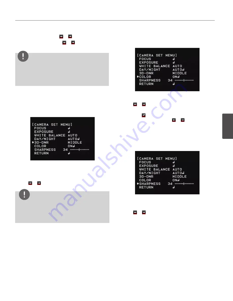
Color setting

You can switch the displayed picture to grayscale or color.

1.   Select the [COLOR] option on the [CAMERA SET] menu.
2.   Use   or   button to change a color effect.

•  ON: To display the picture with color. Select ON and 

press   to display the submenu. You can adjust 
the color level using the   or   button.

•  OFF: To display the picture with grayscale.

Sharpness setting

Sharpens the image outline.

1.   Select the [SHARPNESS] option on the [CAMERA SET] 

menu.

2.   Use   or   button to adjust the option. If you set the 

sharpness value to higher, the image outline becomes 
sharp. If you set to lower value, the image outline 
becomes dim.

Summary of Contents for LW9226 Series

Page 1: ...d this manual carefully before operating your set and retain it for future reference OWNER S MANUAL Network Dome Camera MODELS LW9228 Series LW9228I Series LW9226 Series LW9226I Series P NO MFL67122201 1104 V1 5 ...

Page 2: ...FORMATION FCC Part 15 This equipment has been tested and found to comply with the limits for a Class A digital device pursuant to Part 15 of the FCC Rules These limits are designed to provide reasonable protection against harmful interference when the equipment is operated in a commercial environment This equipment generates uses and can radiate radio frequency energy and if not installed and used...

Page 3: ...ins cord plug When installing the product ensure that the plug is easily accessible LG Electronics hereby declares that this these product s is are in compliance with the essential requirements and other relevant provisions of Directive 2004 108 EC 2006 95 EC and 2009 125 EC European representative LG Electronics Service Europe B V Veluwezoom 15 1327 AE Almere The Netherlands Tel 31 0 36 547 8888 ...

Page 4: ...damaged in any way such as power supply cord or plug is damaged liquid has been spilled or objects have fallen into the apparatus the apparatus has been exposed to rain or moisture does not operate normally or has been dropped Safety Precautions Do not attempt to disassemble the camera To prevent electric shock do not remove screws or covers There are no user serviceable parts inside Ask a qualifi...

Page 5: ... exposed to direct sunlight or rain Do not install the camera near the air outlet of an air conditioner Near a swimming pool or other areas where chemicals are used Food preparation areas and other locations where there are large amounts of steam vapor and oil in flammable atmospheres other special environments Areas where radiation X rays strong electric waves or magnetism is generated At sea in ...

Page 6: ... Connecting power source 16 Connecting Microphone and Speaker Device 17 Mounting the camera 17 Removing the Protection Tape 17 Surface mount optional 19 Ceiling mount optional 21 Wall mount optional 23 Pendant mount optional 4 Operation and settings 27 Before using the system 27 Recommended PC Requirements 28 Accessing the LG IP device 29 LG Smart Web Viewer Overview 30 Configuring the LG IP camer...

Page 7: ... Color setting 49 Sharpness setting 50 PAN TILT Settings 50 Privacy Mask setting 50 Special setting 52 OSD Settings 52 User title setting 52 ZOOM MAG setting 52 FUNCTION setting 52 DOME ID setting 53 LANGUAGE Setting 53 RESET Setting 53 Information 53 Initialization 53 Factory reset 5 Reference 54 Troubleshooting 56 Open source software notice 6 Appendix 58 Specifications ...

Page 8: ...that the operator can program to be linked together in a sequence Pattern recording function A routine of manual operations can be stored and reproduced repeatedly The Pan Tilt and Zoom controls are available for pattern recording NOTE The available total time of pattern differs depending on camera s operation When the pattern recording is full the pattern recording will automatically stop Privacy...

Page 9: ...ype DSS Digital Slow Shutter function It is possible to highly sensitive surveillance because of DSS Digital Slow Shutter function WDR Wide Dynamic Range function The camera can be best condition to watch easily inside or outside in the strong back light Power Supply This camera must always be operated a AC 24 V Certified Listed class 2 power supply only Auto Tracking This feature enables the came...

Page 10: ...a Port B RJ 45 Output data port for alarm relay signal e AUDIO IN Line Level Input Input for a mono microphone or a line in mono signal f AUDIO OUT Line Level Output Connect to an active speaker with a built in amplifier g Power input jack Connects to a AC 24 V power supply using proper cables h ETHERNET Port Connects to a PC or a network via a hub with a 10 BASE T 100 BASE TX cable attached RJ 45...

Page 11: ... data communication is not available d Data Port B RJ 45 Output data port for alarm relay signal e AUDIO IN Line Level Input Input for a mono microphone or a line in mono signal f AUDIO OUT Line Level Output Connect to an active speaker with a built in amplifier g Power input jack Connects to a AC 24 V power supply using proper cables h ETHERNET Port Connects to a PC or a network via a hub with a ...

Page 12: ...s and should conform to all local codes Before you install and connect the camera check and prepare the required peripheral devices and cables Before you connect the camera turn off all devices to be connected such as this camera and DVR Do not touch the dome cover s window Basic Connection Overview LW9226I 9228I series for Indoor LW9226 9228 series for outdoor 3 Installation ...

Page 13: ... Connect the alarm device to the RJ 45 Adapter cable When connecting lines check and connect the color lines of the each device correctly Refer to the below tables for color line information CAUTION Do not connect one alarm sensor to the several camera s alarm input connector Alarm input connection E D C B A G F H PORT A RJ 45 Adapter cable Alarm device Alarm device Alarm device Alarm device Alarm...

Page 14: ...output at an event occurrence You can set the Alarm Output to the normal open or normal close mode 1 Connect the RJ 45 Adapter cable to the PORT B RJ 45 cable of the camera 2 Connect the alarm device to the RJ 45 Adapter cable When connecting lines check and connect the color lines of the each device correctly Refer to the below tables for color line information Alarm Out connection E D C B A G F ...

Page 15: ...rown ALARM OUT COM2 Red ALARM OUT NC2 Orange NC CAUTION Output specifications are lowactive open collector and a drive capacity of 30 V DC 0 5 A maximum Connecting the alarm out incorrectly may cause damaging the camera Connecting Network You can control and monitor the system via network With the remote control monitoring you can change the system configuration or monitor the image via net work A...

Page 16: ...t a AC 24 V power source to the power input terminal as shown below Connecting Microphone and Speaker Device Optionally connect an active speaker and or external microphone with a built in amplifier NOTE Keep the microphone away from the speaker to avoid howling ...

Page 17: ...26I 9228I series models 1 Press the Dome Cover open button and then disassemble the dome cover by using ALIGN mark 2 Remove the protection tape and attach the dome cover CAUTION You must align the OPEN and LOCK mark correctly when you turn the dome cover to open or close If you do not align the mark it causes a malfunction Surface mount optional Follow the instructions below to surface mount the c...

Page 18: ...the surface mounting bracket by following step a and b Align the locking point of the surface mounting bracket and the camera 4 Tighten the locking screw 5 Connect the cables to the cable jacks of the camera body After installing the camera you should arrange the cables using the outlet box to protect the cables ...

Page 19: ... through the ceiling as shown below Ø 166 mm 2 Fasten the safety cable to the building superstructure The building superstructure can vary depending on your installation environment 3 Install the ceiling mounting bracket on the ceiling Face the front of the ceiling mounting bracket toward the area of interest m 4 Tighten the screws until the ceiling mounting bracket holds the ceiling firmly ...

Page 20: ...ounting bracket by following step a and b Align the locking point of the surface mounting bracket and the camera 7 Tighten the locking screw 8 Connect the cables to the cable jacks of the camera body After installing the camera you should arrange the cables using the outlet box to protect the cables CAUTION Do not expose the connected part of the camera cable jacks in the rain or moisture ...

Page 21: ...ional Install the camera by the following order 1 Disassemble the PIPE Installation Bracket to remove the A part A 2 Install the PIPE Installation Bracket to the Wall Mount assembly 3 Connect the safety cable to the wall mount assembly Red Stripe ...

Page 22: ...gh the wall mount assembly so that they hang down 5 Install the wall mount assembly 6 Connect the connection cable and the safety cable to the camera body 7 Attach the camera to the camera assembly bracket by following step a and b Align the locking point of the wall mount assembly and the camera 8 Tighten the locking screw ...

Page 23: ...racket direct to the other type LG Wall Mount assembly This LG Wall Mount assembly make to easy to install your camera Pendant mount optional Install the camera by the following order 1 Disassemble the PIPE Installation Bracket to remove the A part A 2 Install the PIPE Installation Bracket to the Pendant Mount assembly ...

Page 24: ...tallation 3 Connect the safety cable to the pendant mount assembly Red Stripe 4 Drill a hole on the wall where you want to install the pipe Pass the connection cable through the pendant mount assembly so that they hang down ...

Page 25: ...ount assembly 6 Connect the connection cable and the safety cable to the camera body 7 Attach the camera to the camera assembly bracket by following step a and b Align the locking point of the wall mount assembly and the camera 8 Tighten the locking screw ...

Page 26: ... Installation 9 Assemble the camera cover as shown below NOTE You can install the PIPE Installation Bracket direct to the other type LG Wall Mount assembly This LG Wall Mount assembly make to easy to install your camera ...

Page 27: ...Internet Explorer set your browser to allow ActiveX controls If you find this message This website wants to install the following add on IPCam_Streamer cab from LG ELECTRONICS INC Click the yellow bar and install LG Smart Web Viewer Program on your computer The Layouts and the Live view pages may differ with different OS Operating Systems and Web Browsers Care needs to be taken not to run any othe...

Page 28: ...eb Page to start the LG Smart Web Viewer When accessing the LG Smart Web Viewer the authentication dialog appears on the screen 3 3 Enter the user name and password Note that the default administrator user name and password are admin 3 4 Click the OK button and then the LG Smart Web Viewer is displayed in your browser Notes You can also access the LG Smart Web Viewer as shown below 3 1 Start your ...

Page 29: ...the Save button in the Snapshot window 3 Enter the file name JPEG format and select the folder to save it 4 Click the Save button to confirm it 5 Click the Close button in the Snapshot window to close it Displays the Camera OSD control window Use these buttons to setup the Camera This button does not appear on the screen if the login is other than the administrator Displays the PTZ control window ...

Page 30: ...y scale icon Off Click this button to switch the microphone off and on for the computer Color icon On Gray scale icon Off Click this button to switch the sound off and on for the speaker of the computer Color icon On Gray scale icon Off Configuring the LG IP camera The features and options of the LG IP camera are config ured through the Configuration menu Only administrator level users have permis...

Page 31: ... current date and time of the IP device Save Click this button to confirm the settings Maintenance System reboot Click the Reboot button to restart the IP device It takes some minutes for the IP device to start again Restore and backup Backup To take a backup all of the settings If necessary it make possible to return to a backuped configuration Click this button and follow the instructions on the...

Page 32: ...activity in a file View Log Click this button to display the system log information View report Click this button to display the report of the system Language Language list Select a language for the LG Smart Web Viewer configuration menu and information display Save Click this button to confirm the settings Audio Video settings Camera Preview You can preview the camera image on the preview window ...

Page 33: ... format only Quality Select the Quality VBR The bit rate may vary depending on the complexity of the video to meet the selected quality CBR The video quality may vary in order to preserve a constant bit rate Stream quality If the Quality option set to VBR this option is displayed Select the stream quality from the drop down box the camera supports five types Highest High Medium Low and Lowest Bit ...

Page 34: ...m the settings Pattern You can activate the camera in a repeating pattern The pattern is programmed by recording your manual pan tilt and zoom operations The camera stores the movements you performed in memory To record the pattern 1 Click the Start recording button to start the pattern recording 2 Move the camera through the desired movement 3 Click the Stop recording button to stop the pattern r...

Page 35: ... 3 Click the Remove button 4 Repeat the steps 2 to 3 to remove other preset index number 5 Repeat the stpes 1 to 4 to set the other group index To tour the group 1 Enter the group number in the Group index option 2 Click the Play button to start the group tour 3 Click the Stop button to stop the group tour To delete a group 1 Enter the group number in the Group index option 2 Click the Clear butto...

Page 36: ...n Select the HTTP or HTTPS option for security NOTE The RTSP port number should not be same with the web port number TTL TTL This option indicates the Time To Live of multicast packets The default setting is 7 and the allowed TTL range is from 1 to 255 ARP Ping Enable ARP Ping to configure IP address Check to enable ARP ping Save Click this button to confirm the settings RTP stream RTP Real time T...

Page 37: ...address Subnet mask and default gateway manually IP address Enter an IP address Subnet mask Enter a subnet mask address Gateway Enter the gateway address DNS server status Primary DNS server Enter the Primary domain name server that translates the hostnames into IP address Secondary DNS server Enter the Secondary DNS server address that backups the Primary DNS Save Click this button to confirm the...

Page 38: ...address 1 Select the alias from the list 2 Click the Remove button The IP address will be deleted User settings Basic The IP device is shipped with the login rights of administrator only If others need to access the IP device excluding the configuration a login with viewer rights need to be created A maximum of 50 users can be created User list Add the User You can register a new user with various...

Page 39: ...nonymous user login allows the user access for only viewing the live stream image Maximum RTP stream connection Maximum number of simultaneous stream connection Set this number to limit the number of simultane ous stream connections The connections depend on the stream configu ration as shown in the following Maximum RTP stream connection by stream configuration Video Codec Resolution Frame Rate Q...

Page 40: ...ication messages FTP server list Image files can be transferred to the FTP server within the scheduled time Image file that has been recorded linked to an external event is sent to the FTP server periodically To add the FTP server 1 Click the Add button FTP server setting window is displayed 2 Set the FTP server options Alias Type the FTP Server name to upload the image files Address Enter the FTP...

Page 41: ...Type the recipients e mail address You can specify only one recipient e mail address Administrator address Type the e mail address of the administrator Subject Enter the subject title of the e mail Message This message can describe the information of the acquired IP address etc Test Select Test to test the SMTP server 3 Click the Save button to confirm the settings To edit the SMTP server 1 Choose...

Page 42: ...ng object is detected the camera tracks the object until the lost state If a moving object is not detected for the dwell time it goes to the next preset position While it is moving to the next position the Auto Tracking is stopped temporary Because of the OSD Auto Tracking might operate incorrectly while PRESET TOUR GROUP TOUR AUTO PAN About Auto Tracking The Auto Tracking is stopped when a user m...

Page 43: ...S MODE AUTO MANUAL ONE PUSH ZOOM TRIG FOCUS DIST LW9228 series 50 CM 1 8 M 3 M 6 M LW9226 series 50 CM 1 M 3 M 5 M RETURN EXPOSURE IRIS AUTO MANUAL AGC OFF LOW MIDDLE HIGH WDR BLC OFF WDR BLC HSBLC BRIGHTNESS 0 to 100 SHUTTER OFF A FLK 1 160 X2 AUTO SENS UP AUTO X2 AUTO X3 AUTO X128 OFF RETURN WHITE BALANCE ATW AUTO MANUAL COLOR TEMP INDOOR OUTDOOR RED 100 to 100 BLUE 100 to 100 RETURN ONE PUSH DA...

Page 44: ...ER 1 to 8 SET MASK MASK STATE ON OFF MASK COLOR GRAY WHITE BLACK WIDTH 2 to 320 HEIGHT 3 to 240 RETURN SPECIAL PROPORTIONAL PT ON OFF COMPASS SET ON OFF HOME POSITION ON SET GO DWELL TIME 0 to 100 RETURN OFF AUTO RETURN ON RETURN TIME 1 MIN to 100 MIN OFF TILT LIMIT ON OFF RETURN RETURN OSD SET USER TITLE ON OFF ZOOM MAG ON OFF FUNCTION ON OFF DOME ID ON OFF RETURN ...

Page 45: ...Operation and settings 45 4 Operation and settings LANGUAGE The option depends on the model RESET INFORMATION INITIALIZATION FACTORY RESET RETURN RETURN ...

Page 46: ...lected in the menu button Executes selections and displays a submenu for an item with the mark Camera menu settings Focus setting The camera adjusts the focus automatically by sensing the center of the picture Focus mode Select FOCUS MODE option on the FOCUS menu then select the following mode AUTO Auto focus is activated automatically MANUAL Focus is activated automatically after the zoom movemen...

Page 47: ...XPOSURE menu 2 Use or button to select a mode then press WDR LEVEL WDR Wide dynamic range feature can be very helpful to cope with very challenging lighting conditions It is capable of capturing both of the dark part and bright part and combining the differences into a scene to generate a highly realistic image as original scene Set the WDR level LOW MIDDLE HIGH BLC LEVEL Camera s backlight compen...

Page 48: ...ance is approximately from 1 800 to 10 500 K Proper white balance may not be obtained under the following conditions When the color temperature is out of the 1 800 K to 10 500 K range When the scene mostly contains high color temperature objects such as a blue sky or sunset When the scene is dim AUTO In this mode the color temperature range for the proper white balance is approximately 2 700 K to ...

Page 49: ...ct an option NOTE If you set the AGC to OFF on the EXPOSURE menu the 3D DNR function is not available When you use this function the afterimage may occur Color setting You can switch the displayed picture to grayscale or color 1 Select the COLOR option on the CAMERA SET menu 2 Use or button to change a color effect ON To display the picture with color Select ON and press to display the submenu You...

Page 50: ...e mask zone box 9 Select the HEIGHT option and use or button to adjust the vertical size of the mask zone box 10 Repeat steps 3 to 9 to add additional positions NOTE The parts with the registered mask numbers from 1 to 4 have the same color So do the parts with the numbers from 5 to 8 If you change the mask color the registered mask color will be changed automatically with the same color for each ...

Page 51: ... SPECIAL menu 2 Use or button to set it ON 3 Press button 4 Select GO option and then press button The camera will move to the home position NOTE If you do not want to use the home position function set the HOME POSITION option to OFF If you set the HOME POSITION to ON the AUTO RETURN option is set to OFF automatically and you can not use it Auto return This function can be used to specify automat...

Page 52: ... exit the settings ZOOM MAG setting Displays or removes the zoom OSD on the screen 1 Select ZOOM MAG option on the OSD menu 2 Use or button to set it ON or OFF 3 Select RETURN option and press button to exit the setting menu FUNCTION setting Displays or removes the Function OSD on the screen 1 Select FUNCTION option on the OSD menu 2 Use or button to set it ON or OFF 3 Select RETURN option and pre...

Page 53: ...u 2 Press button to display the current camera information Initialization You can initialize the camera settings 1 Select INITIALIZATION option on the RESET menu 2 Press button then confirmation window is displayed 3 Select YES and press button Factory reset Clear certain settings and information and return to factory default settings 1 Select FACTORY RESET option on the RESET menu 2 Press button ...

Page 54: ...ic IP address and if the DHCP option is set then there may be IP s same as the network device and other network partner Hence set the static IP address to 0 0 0 0 to resolve this conflict Cannot access the camera from browser Reconnect the network camera with power and check the ping operation to know if the IP is used by others Disable the proxy setting in the Browser if you are using a proxy ser...

Page 55: ...he system administrator for sufficient bandwidth available or reduce the number of applications running on the client computer If the client PC s are unable to access the multicast stream check with the system administrator for the use of a valid multicast address or check if the router is supporting multicasting If the images appear to have white of gray stripes on it upgrade the Video graphics d...

Page 56: ...f the Apache license from http www apache org licenses LICENSE 2 0 html This product includes dhcp client Copyright 2004 2008 by Internet Systems Consortium Inc ISC Copyright 1995 2003 by Internet Software Consortium expat library copyright 2006 expat maintainers libcap libjpeg Independent JPEG Group Copyright 1991 1998 Thomas G Lane libmd5 Copyright 2002 Aladdin Enterprises libncurses Copyright 1...

Page 57: ...sh distribute sublicense and or sell copies of the Software and to permit persons to whom the Software is furnished to do so subject to the following conditions THE SOFTWARE IS PROVIDED AS IS WITHOUT WARRANTY OF ANY KIND EXPRESS OR IMPLIED INCLUDING BUT NOT LIMITED TO THE WARRANTIES OF MERCHANTABILITY FITNESS FOR A PARTICULAR PURPOSE AND NONINFRINGEMENT IN NO EVENT SHALL THE AUTHORS OR COPYRIGHT H...

Page 58: ...p OFF True Day Night O WDR O Image Enhancement Backlight Compensation Exposure Control Sens Up Control AGC White Balance Privacy Masking EIS Digital Zoom PTZ Optical Zoom x27 x37 Panning Range Speed 0 to 360 Maximum 400 Second Tilting Range Speed 0 to 180 Maximum 400 Second Auto Panning Maximum 8 points Preset 128 Group Touring Maximum 9 Groups Pattern 1EA Auto Tracking O Video Audio Video Compres...

Page 59: ...TTPS RTP RTSP UDP DHCP FTP SMTP NTP ARP ICMP DDNS LG Remote S W LSS464 and Web Client Connections Up to 10 Misc Protection IP66 Vandal Proof IP66 Vandal Proof Power Source AC 24 V Power Consumption 25 W 19 W 25 W 19 W Operating Temperature 20 C to 50 C 10 C to 50 C 20 C to 50 C 10 C to 50 C Humidity 0 RH to 80 RH Safekeeping Temperature 30 C to 60 C Humidity 0 RH to 90 RH Weight 4 17 kg 2 5 kg 4 1...

Page 60: ...BZ03 ...

Reviews: