3. TECHNICAL BRIEF
- 35 -
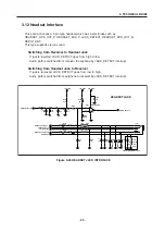
Figure 3-18 AD6537B BATTERY CHARGING BLOCK
AD6537B
Control
Serial
Port
CSFS
CSDI
CSDO
Charge
Timer
Trouble
Charge
Chg.
DAC
VCHG
GATEDRIVE
ISENSE
VBATSENSE
VBATx
BATTYPE
REFCHG
R
TRIF
R
SENSE
AGND1
TEMP2
VCHARGER
R
GATE
4-Terminal Battery Pack
R
TEMP
thermistor
R
TEMP
resistor
INT
Interrupt
Logic
Aux
ADC
3. Battery Charging Block
1. It can be used to charge Lithium Ion and/or Nickel Metal Hydride batteries.
Charger initialization, trickle charging, and Li-Ion charging control are implemented in
hardware.
2. Charging Process
- Check charger is inserted or not
- If AD6537B detects that Charger is inserted, the CC-CV charging starts.
- Exception : When battery voltage is lower than 3.2V, the precharge
(low current charge mode) starts firstly.
- And the battery voltage reach to 3.2V the CC-CV charging starts.
3. Pins used for charging
- VCHG
: charger supply.
- GATEDRIVE : charge DAC output
- ISENSE
: charge current sense input
- VBATSENSE : battery voltage sense input.
- BATTYPE
: battery type identification input
- REFCHG
: voltage reference output
4. TA (Travel Adaptor)
- Input voltage
: AC 85V ~ 260V, 50~60Hz
- Output voltage : DC 5.2V (0.2 V)
- Output current : Max 800mA (50mA)
5. Battery
- Li-ion battery (Max 4.2V, Nom 3.7V)
- Standard battery: Capacity -830mAh
Summary of Contents for B2070
Page 68: ... 67 4 TROUBLE SHOOTING TEST POINT 4 6 LCD Trouble ...
Page 72: ... 71 4 TROUBLE SHOOTING TEST POINT 4 8 Speaker Trouble ...
Page 79: ... 78 4 TROUBLE SHOOTING 4 11 KEY backlight Trouble TEST POINT ...
Page 107: ... 106 8 PCB LAYOUT Figure 8 1 B2070 BOTTOM SIDE PCB LAYOUT ...
Page 108: ... 107 8 PCB LAYOUT Figure 8 1 B2070 TOP SIDE PCB LAYOUT ...
Page 109: ... 108 ...
Page 117: ...10 STAND ALONE TEST 116 Figure 10 2 HW test setting Figure 10 3 Ramping profile ...
Page 121: ... 120 ...
Page 123: ... 122 ...


