3. TECHNICAL BRIEF
- 28 -
3.6 Analog Main & Power Management Processor (AD6537B, U101)
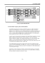
Figure 3-11 AD6537B FUNCTION BLOCK DIAGRAM
AD6525
or
AD6526
AD6537B
Light
Controllers
T
R
O
P
S
C
Ram
GMSK
Filter
Filter
Filter
Filter
Tone
ADC
ADC
ADC
DAC
DAC
ADC
DAC
DAC
DAC
T
R
O
P
S
B
T
R
O
P
S
A
h
cti
w
S
Mic
Headphones
or Headset
Battery
Charger
8 Voltage Regulators
Othello
LEDs
Crystal &
Varactor
VCORE: 1.8 V, 80mA
VMEM: 1.8 or 2.8V, 150mA
VEXT: 2.8V, 170mA
VSIM: 1.8 or 2.85V, 20mA
VRTC: 1.8V, 200 µA
VABB
VMIC: 2.5V, 1mA
VVCXO: 2.75V, 10mA
Summary of Contents for B2070
Page 68: ... 67 4 TROUBLE SHOOTING TEST POINT 4 6 LCD Trouble ...
Page 72: ... 71 4 TROUBLE SHOOTING TEST POINT 4 8 Speaker Trouble ...
Page 79: ... 78 4 TROUBLE SHOOTING 4 11 KEY backlight Trouble TEST POINT ...
Page 107: ... 106 8 PCB LAYOUT Figure 8 1 B2070 BOTTOM SIDE PCB LAYOUT ...
Page 108: ... 107 8 PCB LAYOUT Figure 8 1 B2070 TOP SIDE PCB LAYOUT ...
Page 109: ... 108 ...
Page 117: ...10 STAND ALONE TEST 116 Figure 10 2 HW test setting Figure 10 3 Ramping profile ...
Page 121: ... 120 ...
Page 123: ... 122 ...

