48
August 2009 Plasma 50PS80
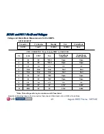
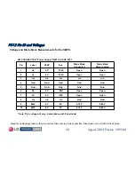
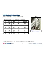
Diode Mode Readings taken with all connectors Disconnected.
Black lead on Gnd. DVM in Diode Mode.
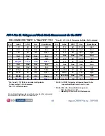
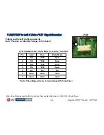
P814 Pins ID, Voltages and Diode Mode Measurements for the SMPS
P814 Pins ID, Voltages and Diode Mode Measurements for the SMPS
Open
3.3V
0V
M5 ON
21
Open
5V
5V
Stby 5V
23
Open
3.3V
0V
RL On
19
1.45V
4.8V
0V
5V Det
17*
Gnd
Gnd
Gnd
Gnd
15
Gnd
Gnd
Gnd
Gnd
13
Open
5.15V
5.15V
Stby 5V
11
1.2V
5.15V
0V
+5V
9
Gnd
Gnd
Gnd
Gnd
7
Open
12V
0V
12V
5
Gnd
Gnd
Gnd
Gnd
3
2.2V
17.3V
0V
17V
1*
Diode Mode
Run
STBY
Label
Pin
Open
Gnd
Gnd
Auto Gnd
22
Open
*0V
*0V
Key On
24*
Open
3.2V
0V
VS On
20
1.45V
5V
5V
AC Det
18*
n/c
n/c
n/c
n/c
16
Gnd
Gnd
Gnd
Gnd
14
1.2V
5.15V
0V
+5V
12
1.2V
5.15V
0V
+5V
10
Gnd
Gnd
Gnd
Gnd
8
Open
12V
0V
12V
6
Gnd
Gnd
Gnd
Gnd
4
2.2V
17.3V
0V
17V
2*
Diode Mode
Run
STBY
Label
Pin
P814 CONNECTOR “SMPS" to “Main PWB" P1108
* Pin 24: When the Power Button is opened,
•
Pin 24 pulls up to 4.3V.
•
Stand-By
5V
turns off. AC-Det remains.
* Pin 1 and 2: 17V If Vs is unloaded will pulsate.
Turned on by Vs On Command.
* Pin 18: AC DET if missing will cause the set to be
inoperative. Main board held in reset.
* Pin 17: 5V Det not used.
* Pins 9, 10, 12: (+5V) Turned on by Relay On Command.


