83
August 2009 Plasma 50PS80
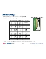
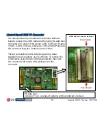
P100 Pin ID and Voltages
P100 Pin ID and Voltages
Open
Gnd
Gnd
10
Open
0.4V
SUS-UP
11
Open
0.7V
SUS-DN
12
Open
3V
Z Bias
9
Gnd
Gnd
Gnd
8
Open
0V
ER-DN
7
Open
0V
ER-UP
6
Open
0V
CTRL-OE
5
1.9V
17.8V
15V
4
1.9V
17.8V
15V
3
1.9V
17.8V
15V
2
1.9V
17.8V
15V
1
Diode Mode
Run
Label
Pin
Diode Mode Readings taken with all connectors Disconnected. Black lead on Gnd. DVM in Diode Mode.
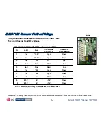
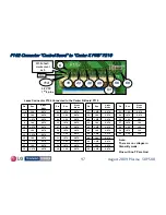
P100 CONNECTOR "Z-SUS PWB” to “Control Board” P2
1
Note: Black wire is NOT pin 1.
Voltage and Diode Mode Measurements for the Z-SUS PWB.
This board has no Stand-By voltages.


