91
August 2009 Plasma 50PS80
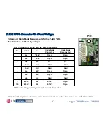
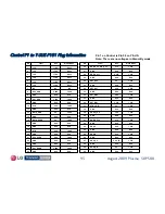
Control Board LVDS P5 Connector Voltages and Diode Check
Control Board LVDS P5 Connector Voltages and Diode Check
1.3V
0V
23
1.3V
0V
20
1.3V
0V
22
1.3V
1.2V
17
1.3V
1.2V
19
1.3V
1.3V
15
1.3V
1.1V
16
1.3V
1.1V
23
1.3V
1.0V
14
1.3V
1.1V
13
1.3V
1.2V
12
1.3V
1.2V
6
1.3V
1.1V
5
1.3V
1.2V
6
1.3V
1.1V
5
1.3V
0V
3
1.3V
0V
2
Diode Mode
Run
Pin
15
15
5
5
2
2
Open
3.3V
42
Open
3.3V
40
Open
3.3V
41
Open
1.1V
38
Open
1.2V
39
1.3V
1.1V
35
1.3V
1.2V
36
Open
0.58V
43
1.3V
1.2V
33
1.3V
1.1V
32
1.3V
1.1V
31
1.3V
1.2V
30
1.3V
1.1V
29
1.3V
1.2V
28
1.3V
1.2V
27
1.3V
1.1V
26
1.3V
1.2V
25
Diode Mode
Run
Pin
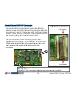
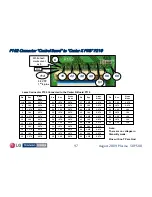
P5 Connector "Control Board” to “Main PWB” P203
Note: There are no voltages in Stand-By mode.
Gnd
Gnd
P5
20
20
25
25
30
30
35
35
40
40
51
51
Gnd
Gnd
Pins 7~10, 47~51 are n/c
Pins 1, 11, 18, 21, 34, 37, 44~46 are Gnd
Blue Pins indicate 24 bit
(12 bit differential) video signal


