57
August 2009 Plasma 50PS80
Observing (Capturing) the Y
Observing (Capturing) the Y
-
-
Drive Signal for Set
Drive Signal for Set
-
-
up or Set
up or Set
-
-
down
down
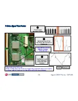
Fig 1:
As an example of how to lock in to the Y-Drive Waveform.
Fig 1 shows the signal locked in at 2ms per/div.
Note the blanking sections.
The signal for Set-Up / Down adjustment is outlined within
the Waveform
Fig 2:
At 100us per/div. the signal for Set-Up / Down adjustment is
now easier to recognize. It is outlined within the Waveform
Fig 3:
At 50uSec per/division, the adjustment for
SET-UP or SET-DOWN
can be made.
Note: When actually performing the adjustments,
The portion of the waveform being adjusted can be
Zoomed in on by increasing the speed of the scope.
FIG1
2mS
FIG2
100uS
Outlined
Area
Blanking
FIG3
50uS
Set must be in “
WHITE WASH
” All other DC Voltage
adjustments should have already been made.
Set Up
Set Down
Area to
be adjusted
Area to
be adjusted


