99
August 2009 Plasma 50PS80
X BOARD (LEFT, RIGHT and CENTER) SECTION
X BOARD (LEFT, RIGHT and CENTER) SECTION
The following section gives detailed information about the X boa
The following section gives detailed information about the X boa
rds.
rds.
These boards deliver the Color information signal developed on t
These boards deliver the Color information signal developed on t
he
he
Control board to the TCPs, (Taped Carrier Packages). The TCPs ar
Control board to the TCPs, (Taped Carrier Packages). The TCPs ar
e
e
attached to the vertical FPCs, (Flexible Printed Circuits) which
attached to the vertical FPCs, (Flexible Printed Circuits) which
are
are
attached directly to the panel. The X boards are the attachment
attached directly to the panel. The X boards are the attachment
points for these FPCs.
points for these FPCs.
These boards have no adjustment.
These boards have no adjustment.
These boards receive their main B+ from the:
These boards receive their main B+ from the:
•
•
Originally developed on the Switched Mode Power Supply
Originally developed on the Switched Mode Power Supply
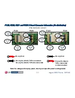
Va (Voltage for Address) is routed through the Y
Va (Voltage for Address) is routed through the Y
-
-
SUS board
SUS board
and then to the Left X board via P121 pins 1~4. Va also
and then to the Left X board via P121 pins 1~4. Va also
leaves P120 and is sent to the Center X via P220. Then it
leaves P120 and is sent to the Center X via P220. Then it
leaves on P221 and goes to the Right X P320.
leaves on P221 and goes to the Right X P320.
•
•
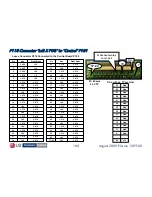
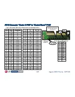
Control board develops 3.3V and routes to each X board via
Control board develops 3.3V and routes to each X board via
ribbon connectors P110, P210 and P310.
ribbon connectors P110, P210 and P310.

