4026-0XX
Diagnostic Information 2-23
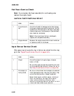
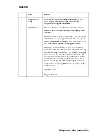
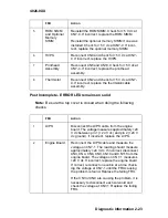
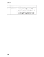
Post Incomplete - ERROR LED remains on solid
Note: Be sure the top cover is closed when doing the following
checks.
5
ROM SIMM
and Optional
Memory
SIMM
Reinstall the ROM SIMM. Check for +5 V dc at
CN7-4. If incorrect, replace the ROM SIMM.
Reinstall the optional memory SIMM if one was
installed. Check for +5 V dc at CN7-4. If incor-
rect, replace the optional memory SIMM.
6
HVPS
Reconnect CN4 and check for +5 V dc at CN7-
4. If incorrect, replace the HVPS.
7
Printhead
Assembly
Reconnect CN5 and CN10. Check for +5 V dc at
CN7-4. If incorrect, replace the printhead
assembly.
8
Thermistor
Reconnect CN2 and check for +5 V dc at CN7-
4. If incorrect, replace the thermistor/cable
assembly.
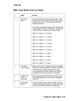
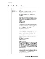
FRU
Action
1
LVPS
Disconnect the LVPS cable from the engine
board. The voltage measures approxi24
V dc between pin 1 (+24 V dc) and pin 2 (+24 V
dc ground). If incorrect, replace the LVPS.
2
Engine Board
Reconnect the LVPS cable and measure the
voltage on CN7-1. The reading should measure
approxi24 V dc. If incorrect, disconnect
CN3, CN4, CN6, CN9, CN10 and CN11 from the
engine board. The voltage on CN7-1 measures
+24 V dc. If incorrect, replace the engine board.
If correct, reconnect one cable at a time check-
ing the voltage at CN7-1 until the FRU causing
the problem is found. Replace the failing FRU.
If the CN3 or CN9 are causing the problem, it is
necessary to disconnect each solenoid and
check the voltage at CN7-1. Replace the failing
FRU.
FRU
Action
Summary of Contents for Optra E
Page 8: ...viii Service Manual 4026 0XX ...
Page 15: ...Notices and Safety Information xv 4026 0XX Japanese Laser Notice Chinese Laser Notice ...
Page 72: ...4026 0XX 3 5 ...
Page 74: ...4026 0XX 3 7 ...
Page 101: ...4026 0XX Connector Locations 5 6 ...
Page 105: ...4026 0XX Connector Locations 5 10 ...
Page 108: ...4026 0XX 6 2 Assembly 1 Covers ...
Page 110: ...4026 0XX 6 4 Assembly 1 Covers continued ...
Page 112: ...4026 0XX 6 6 Assembly 2 Frame ...
Page 114: ...4026 0XX 6 8 Assembly 2 Frame continued ...
Page 116: ...4026 0XX 6 10 Assembly 2 Frame continued ...
Page 118: ...4026 0XX 6 12 Assembly 3 Printhead ...
Page 120: ...4026 0XX 6 14 Assembly 4 Paper Feed Input Tray ...
Page 122: ...4026 0XX 6 16 Assembly 5 Paper Feed Frame ...
Page 124: ...4026 0XX 6 18 Assembly 6 Fuser ...
Page 126: ...4026 0XX 6 20 Assembly 6 Fuser continued ...
Page 128: ...4026 0XX 6 22 Assembly 7 Electronics ...
Page 130: ...4026 0XX 6 24 Assembly 7 Electronics continued ...
Page 132: ...4026 0XX 6 26 Assembly 8 Transfer Assembly ...
Page 134: ...4026 0XX 6 28 Assembly 9 Option Second Paper Drawer ...
Page 136: ...4026 0XX 6 30 Assembly 9 Option Second Paper Drawer continued ...
Page 138: ...4026 0XX 6 32 Assembly 9 Option Second Paper Drawer continued ...

