


4026-0XX
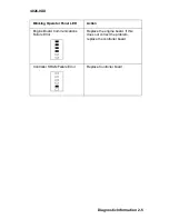
Diagnostic Information 2-15
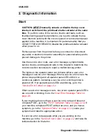
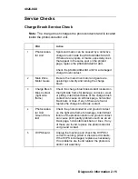
Service Checks
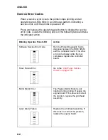
Charge Brush Service Check
Note: The charge brush charges the photoconductor and is located
inside the photoconductor unit.
FRU
Action
1
Photoconduc-
tor Unit
Spots and marks can be caused by a defective
charge brush inside the
photoconductor unit
.
If there are any spots or marks, especially ones
that appear in the same spot on the printed
page, replace the
photoconductor unit
.
Check the
photoconductor unit
for a damaged
charge brush contact.
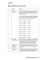
2
Main Drive
Motor Gears
Be sure the main drive motor and gears are
operating correctly and turning the charge
brush.
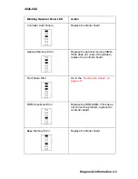
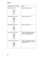
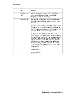
3
Charge Brush
Bias Contact
(right side
frame)
Check the charge brush bias contact located on
the right side frame for damage, corrosion, wear
or pitting. Intermittent failure of the charge brush
contact can cause an all black page, horizontal
black bars or lines. If any of these are found,
replace the charge brush bias contact.
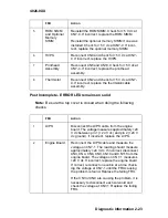
4
Photoconduc-
tor Unit
Ground Con-
tact
Check the photoconductor unit ground contact
on the right side frame for damage. Intermittent
failure of the photoconductor unit ground contact
can cause print quality problems such as an all
black page, horizontal black bars or lines. If any
of these are found, replace the photoconductor
unit ground contact.
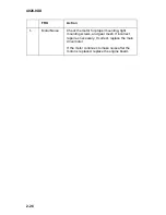
5
HVPS board
Unplug the machine and check the HVPS for
correct mounting, pitted or discolored contacts.
If the HVPS is damaged, replace as necessary.
If no problems are found replace the photocon-
ductor unit assembly.
Summary of Contents for Optra E
Page 8: ...viii Service Manual 4026 0XX ...
Page 15: ...Notices and Safety Information xv 4026 0XX Japanese Laser Notice Chinese Laser Notice ...
Page 72: ...4026 0XX 3 5 ...
Page 74: ...4026 0XX 3 7 ...
Page 101: ...4026 0XX Connector Locations 5 6 ...
Page 105: ...4026 0XX Connector Locations 5 10 ...
Page 108: ...4026 0XX 6 2 Assembly 1 Covers ...
Page 110: ...4026 0XX 6 4 Assembly 1 Covers continued ...
Page 112: ...4026 0XX 6 6 Assembly 2 Frame ...
Page 114: ...4026 0XX 6 8 Assembly 2 Frame continued ...
Page 116: ...4026 0XX 6 10 Assembly 2 Frame continued ...
Page 118: ...4026 0XX 6 12 Assembly 3 Printhead ...
Page 120: ...4026 0XX 6 14 Assembly 4 Paper Feed Input Tray ...
Page 122: ...4026 0XX 6 16 Assembly 5 Paper Feed Frame ...
Page 124: ...4026 0XX 6 18 Assembly 6 Fuser ...
Page 126: ...4026 0XX 6 20 Assembly 6 Fuser continued ...
Page 128: ...4026 0XX 6 22 Assembly 7 Electronics ...
Page 130: ...4026 0XX 6 24 Assembly 7 Electronics continued ...
Page 132: ...4026 0XX 6 26 Assembly 8 Transfer Assembly ...
Page 134: ...4026 0XX 6 28 Assembly 9 Option Second Paper Drawer ...
Page 136: ...4026 0XX 6 30 Assembly 9 Option Second Paper Drawer continued ...
Page 138: ...4026 0XX 6 32 Assembly 9 Option Second Paper Drawer continued ...