


4026-0XX
Diagnostic Information 2-1
2. Diagnostic Information
Start
CAUTION:
NEVER manually actuate or disable the top cover
interlock switch and the printhead shutter actuator at the same
time. To perform some of the service checks and tests, such as
troubleshooting paper feed problems, you need to actuate the top
cover interlock switch with the covers opened or removed and power
applied to the machine. It is important for personal safety that you
DO NOT, FOR ANY REASON, disable the printhead shutter actuator
when power is on.
Remove power from the printer before you connect or disconnect
any cable or electronic board or assembly for personal safety and to
prevent damage to the printer.
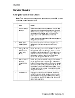
Use the service error code, user error message, symptom table,
service checks, and diagnostic aids in this chapter to determine the
corrective action necessary to repair a malfunctioning printer.
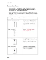
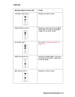
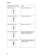
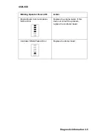
The lights on the operator panel can indicate either a user error
message or service error message. When a service error occurs the
printer stops printing and all operator panel LEDs blink in a
continuous pattern, indicating a service error, until the printer is
powered off. If all operator panel LEDs are blinking, go to the
“Service Error Codes” on page 2-2
.
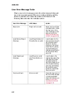
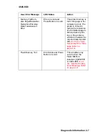
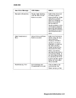
When a user error message occurs, one or two operator panel LEDs
are on solid or blinking. Go to the
“User Error Message Table” on
page 2-6
.
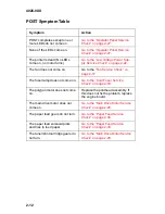
If your machine does not have a service error code and does not
complete POST, go to the
“POST Symptom Table” on page 2-12
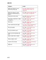
. If
your machine completes POST without an error, and you have a
symptom, go to the
“Symptom Table” on page 2-13
. Locate your
symptom and take the appropriate action.
If a service error code appears while you are working on the
machine, go to the
“Service Error Codes” on page 2-2
and take the
indicated action for that error.
Summary of Contents for Optra E
Page 8: ...viii Service Manual 4026 0XX ...
Page 15: ...Notices and Safety Information xv 4026 0XX Japanese Laser Notice Chinese Laser Notice ...
Page 72: ...4026 0XX 3 5 ...
Page 74: ...4026 0XX 3 7 ...
Page 101: ...4026 0XX Connector Locations 5 6 ...
Page 105: ...4026 0XX Connector Locations 5 10 ...
Page 108: ...4026 0XX 6 2 Assembly 1 Covers ...
Page 110: ...4026 0XX 6 4 Assembly 1 Covers continued ...
Page 112: ...4026 0XX 6 6 Assembly 2 Frame ...
Page 114: ...4026 0XX 6 8 Assembly 2 Frame continued ...
Page 116: ...4026 0XX 6 10 Assembly 2 Frame continued ...
Page 118: ...4026 0XX 6 12 Assembly 3 Printhead ...
Page 120: ...4026 0XX 6 14 Assembly 4 Paper Feed Input Tray ...
Page 122: ...4026 0XX 6 16 Assembly 5 Paper Feed Frame ...
Page 124: ...4026 0XX 6 18 Assembly 6 Fuser ...
Page 126: ...4026 0XX 6 20 Assembly 6 Fuser continued ...
Page 128: ...4026 0XX 6 22 Assembly 7 Electronics ...
Page 130: ...4026 0XX 6 24 Assembly 7 Electronics continued ...
Page 132: ...4026 0XX 6 26 Assembly 8 Transfer Assembly ...
Page 134: ...4026 0XX 6 28 Assembly 9 Option Second Paper Drawer ...
Page 136: ...4026 0XX 6 30 Assembly 9 Option Second Paper Drawer continued ...
Page 138: ...4026 0XX 6 32 Assembly 9 Option Second Paper Drawer continued ...