


4026-0XX
Diagnostic Information 2-33
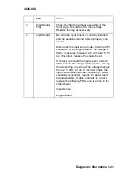
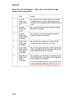
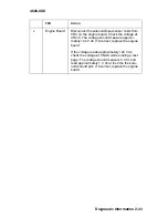
2
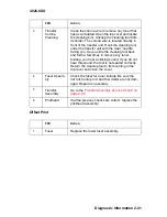
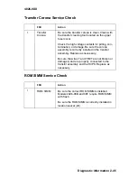
Engine Board
Disconnect the solenoid/input sensor cable from
CN3 on the engine board. Check the voltage at
CN3-5. The voltage should measure approxi-
24 V dc. If incorrect, replace the engine
board.
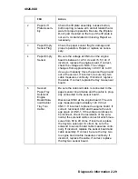
If the voltage reads approxi24 V dc,
check the voltage at CN3-6 while running a test
page. The voltage should measure 0 V dc and
read approximately 1 V dc at the time the sole-
noid should pick. If incorrect, replace the engine
board.
FRU
Action
Summary of Contents for Optra E
Page 8: ...viii Service Manual 4026 0XX ...
Page 15: ...Notices and Safety Information xv 4026 0XX Japanese Laser Notice Chinese Laser Notice ...
Page 72: ...4026 0XX 3 5 ...
Page 74: ...4026 0XX 3 7 ...
Page 101: ...4026 0XX Connector Locations 5 6 ...
Page 105: ...4026 0XX Connector Locations 5 10 ...
Page 108: ...4026 0XX 6 2 Assembly 1 Covers ...
Page 110: ...4026 0XX 6 4 Assembly 1 Covers continued ...
Page 112: ...4026 0XX 6 6 Assembly 2 Frame ...
Page 114: ...4026 0XX 6 8 Assembly 2 Frame continued ...
Page 116: ...4026 0XX 6 10 Assembly 2 Frame continued ...
Page 118: ...4026 0XX 6 12 Assembly 3 Printhead ...
Page 120: ...4026 0XX 6 14 Assembly 4 Paper Feed Input Tray ...
Page 122: ...4026 0XX 6 16 Assembly 5 Paper Feed Frame ...
Page 124: ...4026 0XX 6 18 Assembly 6 Fuser ...
Page 126: ...4026 0XX 6 20 Assembly 6 Fuser continued ...
Page 128: ...4026 0XX 6 22 Assembly 7 Electronics ...
Page 130: ...4026 0XX 6 24 Assembly 7 Electronics continued ...
Page 132: ...4026 0XX 6 26 Assembly 8 Transfer Assembly ...
Page 134: ...4026 0XX 6 28 Assembly 9 Option Second Paper Drawer ...
Page 136: ...4026 0XX 6 30 Assembly 9 Option Second Paper Drawer continued ...
Page 138: ...4026 0XX 6 32 Assembly 9 Option Second Paper Drawer continued ...