


Technical data
Leuze electronic GmbH + Co. KG
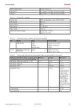
MLC 530 SPG
93
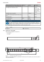
Profile cross section
29 mm x 35.4 mm
Dimensions
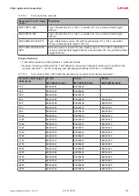
see chapter 15.2 "Dimensions and weights"
Weight
see chapter 15.2 "Dimensions and weights"
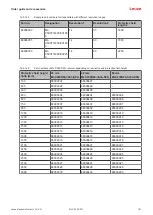
Tab. 15.4:
System data - transmitter
Light source
LED; exempt group in acc. with IEC 62471
Wavelength
940 nm
Pulse duration
800 ns
Pulse pause
1.9 µs (min.)
Mean power
<50 µW
Input current pin 4 (range)
A24 V: 10 mA
Against 0 V: 10 mA
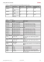
Tab. 15.5:
System data receiver, indication signals and control signals
Pin
Signal
Type
Electrical data
1
RES/STATE
Input:
Output:
Reaction time:
A24 V: 10 mA
Against 0 V: 80 mA
100 ms
3, 4, 8
Depending on the oper-
ating mode
Input:
Against 0 V: 4 mA
A24 V: 4 mA
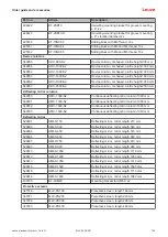
Tab. 15.6:
Technical data of the electronic safety-related switching outputs (OSSDs) on the receiver
Safety-related PNP transistor outputs (short-
circuit monitored, cross-circuit monitored)
Minimum
Typical
Maximum
Switching voltage high active (U
v
- 1.5V)
18 V
22.5 V
27 V
Switching voltage low
0 V
+2.5 V
Switching current
300 mA
380 mA
Residual current
<2 µA
200 µA
In the event of a
failure (if the 0 V
cable is inter-
rupted), each of
the outputs be-
haves as a
120 kΩ resistor
to U
v
. A down-
stream safety
PLC must not de-
tect this as a logi-
cal “1”.
Load capacity
0.3 µF
Load inductivity
2 H


