


Electrical connection
Leuze electronic GmbH + Co. KG
MLC 530 SPG
70
NOTICE
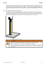
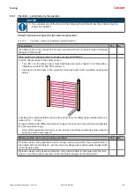
Teach blanking by opening the bridge between pin 1 and pin 8 with a teach key switch and ap-
plying a voltage of +24 V to pin 1 and a voltage of 0 V to pin 8.
1
Optional teach key switch
Fig. 8.4:
Operating mode 1: connection example with Smart Process Gating (SPG)
8.3
Operating mode 4
see chapter 4.4.2 "Operating mode 4 - standard with short tolerance times"
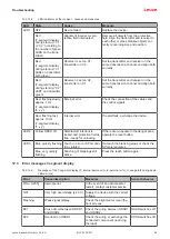
Tab. 8.4:
Pin assignment operating mode 4
Pin
Color
General desc.
Wiring
1
White
IO1/RES
Pin 8 (bridge)
2
Brown
VIN1
24 V
3
Green
IN3
CS
4
Yellow
IN4
TH
5
Gray
OSSD1
OSSD1
6
Pink
OSSD2
OSSD2
7
Blue
VIN2
0 V
8
Red
IN8
Pin 1 (bridge)
FE
-
FE
FE
NOTICE
The timeout of 10 minutes can optionally be extended by another control signal (TH timer hold
signal) from the control to up to 100 hours (see chapter 4.5.2 "Gating timeout extension").


