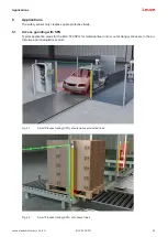
Smart Process Gating
Leuze electronic GmbH + Co. KG
MLC 530 SPG
30
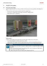
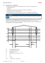
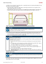
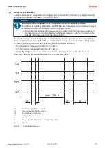
In addition to the functionality of operating mode 1, operating mode 6 also includes partial gating. The top
four beams are excluded from gating.
• With partial gating, unauthorized riding along on the transport material can be recognized, and so-
called pendulum flaps can be monitored.
• With partial gating, the upper four beams are not bridged during a gating process on the side turned
away from the connector. Interruptions of these beams always cause the OSSDs to switch off.
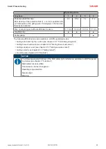
NOTICE
The upper four beams must be free during operation in operating mode 6.
Interruptions cause the OSSDs to switch off.
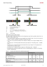
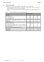
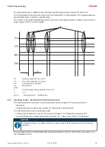
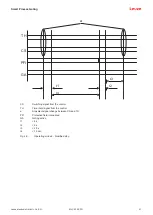
• The gating sequence is initiated by the antivalent signal change between CS and TH within 0.5 s.
• If it is not possible for the protective field to be interrupted within 4 s after initiation of the gating se-
quence, the possibility exists to perform a qualified stop.
NOTICE
Monitoring of pendulum flaps!
If operating mode 6 is to be used to monitor the pendulum flaps, the following additional safety
information must be observed:
Ä
The pendulum flap / swing door must feature a solid design and require tools for disman-
tling.
Ä
The safety door must be designed in accordance with ISO 14120 and ISO 13857. Side ac-
cess without triggering the pendulum flap must not be possible.
Ä
The transport material may not actuate the pendulum flap (e.g., excessive load).
Ä
The transmitter, receiver, pendulum flap/door must be protected against damage, e.g., to
prevent warping or slipping.
Ä
The pendulum flap must not be made of transparent material.
Opening of the pendulum flap (in both directions) must safely interrupt the corresponding
protective field area.
Qualified stop function
NOTICE
The TH timer hold signal from the control must not be generated by inverting the CS switching
signal.
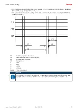
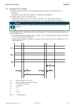
The function of the stop of the gating sequence as well as of the gating restart is initiated by the renewed
edge change of the CS and TH signals.


