Electrical connection
Leuze electronic GmbH + Co. KG
MLC 530 SPG
67
8.1
Pin assignment transmitter and receiver
8.1.1
MLC 500 transmitter
MLC 500 transmitters are equipped with a 5-pin M12 connector.
2
3
1
4
5
FE
VIN1
1
RNG
4
VIN2
3
FE
5
-A1
MLCx00T
n.c.
2
Fig. 8.1:
Pin assignment and connection diagram transmitter
Tab. 8.1:
Pin assignment transmitter
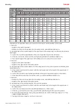
Pin
Core color (CB-M12-xx000E-5GF)
Transmitter
1
Brown
VIN1 - supply voltage
2
White
n.c.
3
Blue
VIN2 - supply voltage
4
Black
RNG - range
5
Gray
FE - functional earth, shield
FE
FE - functional earth, shield
The polarity of the supply voltage selects the transmission channel of the transmitter:
• VIN1 = +24 V, VIN2 = 0 V: transmission channel C1
• VIN1 = 0 V, VIN2 = +24 V: transmission channel C2
The wiring of pin 4 determines the transmitting power and thereby the range:
• Pin 4 = +24 V: standard range
• Pin 4 = 0 V or open: reduced range


