


Device description
Leuze electronic GmbH + Co. KG
MLC 530 SPG
13
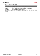
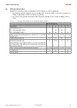
Device type
Transmitter
Receiver
Function
package
Basic
Standard
Ex-
tended
SPG
Model
MLC 500
MLC 501
MLC 500/
A
MLC 502
MLC 510
MLC 511
MLC 510/
A
MLC 520
MLC 530
MLC 530
SPG
SPG
■
Multi-scan
■
■
Range reduc-
tion
■
■
Test input
■
Protective field properties
The beam distance and the number of beams are dependent on the resolution and protective field height.
NOTICE
Depending on the resolution, the effective protective field height can be larger than the optically
active area of the safety sensor housed in yellow (see chapter 3.1 "Device overview of the MLC
family" and see chapter 15.1 "General specifications").
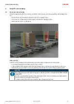
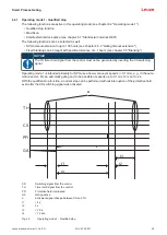
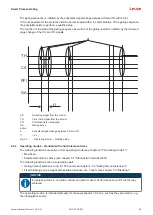
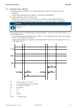
Device synchronization
The synchronization of receiver and transmitter for creating a functioning protective field is done optically,
i.e. without cables, via two specially coded synchronization beams. A cycle (i.e. a pass from the first to the
last beam) is called a scan. The length of a scan determines the length of the response time and affects the
calculation of the safety distance (see chapter 7.1.1 "Calculation of safety distance S").
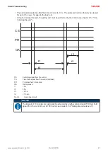
NOTICE
For the correct synchronization and function of the safety sensor, at least one of the two syn-
chronization beams must be free during synchronization and operation.
During the SPG process, an interruption of both synchronization beams up to 60 s is possible
(see chapter 4.1 "Overview and principle").
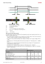
a
b
b
a
Optically active area, housed in yellow
b
Synchronization beams
Fig. 3.1:
Transmitter-receiver system


