


Device description
Leuze electronic
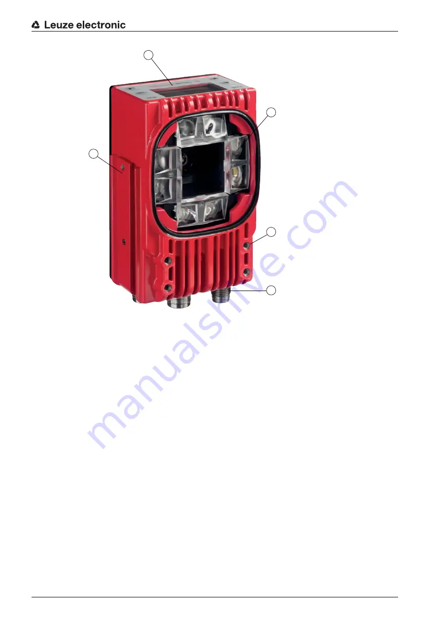
LSIS 472i
9
1
Display and control panel
2
Camera and lighting unit
3
M4 mounting thread
4
Electrical connections
5
Fastening groove
Figure 3.1: Device construction
Markings
The smart camera detects the following markings:
• Hole: dark marking on light background
• Reflector: light marking on dark background
Which markings (hole or reflector) need to be present in the crossbeam of the rack is dependent on the
working distance and the crossbeam:
•
Rack Near
: compartment fine positioning on hole or reflector
•
Rack Far
: compartment fine positioning on reflector
3.1.2 Performance characteristics
The most important performance characteristics of the smart camera:
• Positioning accuracy up to ± 2 mm
• Reading distance 250 mm to 1900 mm
• Integrated IR illumination (850 nm infrared LED)
• Integrated display with control panel for alignment and for fast teaching of the position marking (hole
or reflector).
• Measurement value output:
• 4 digital outputs
• Ethernet
1
2
3
5
4


