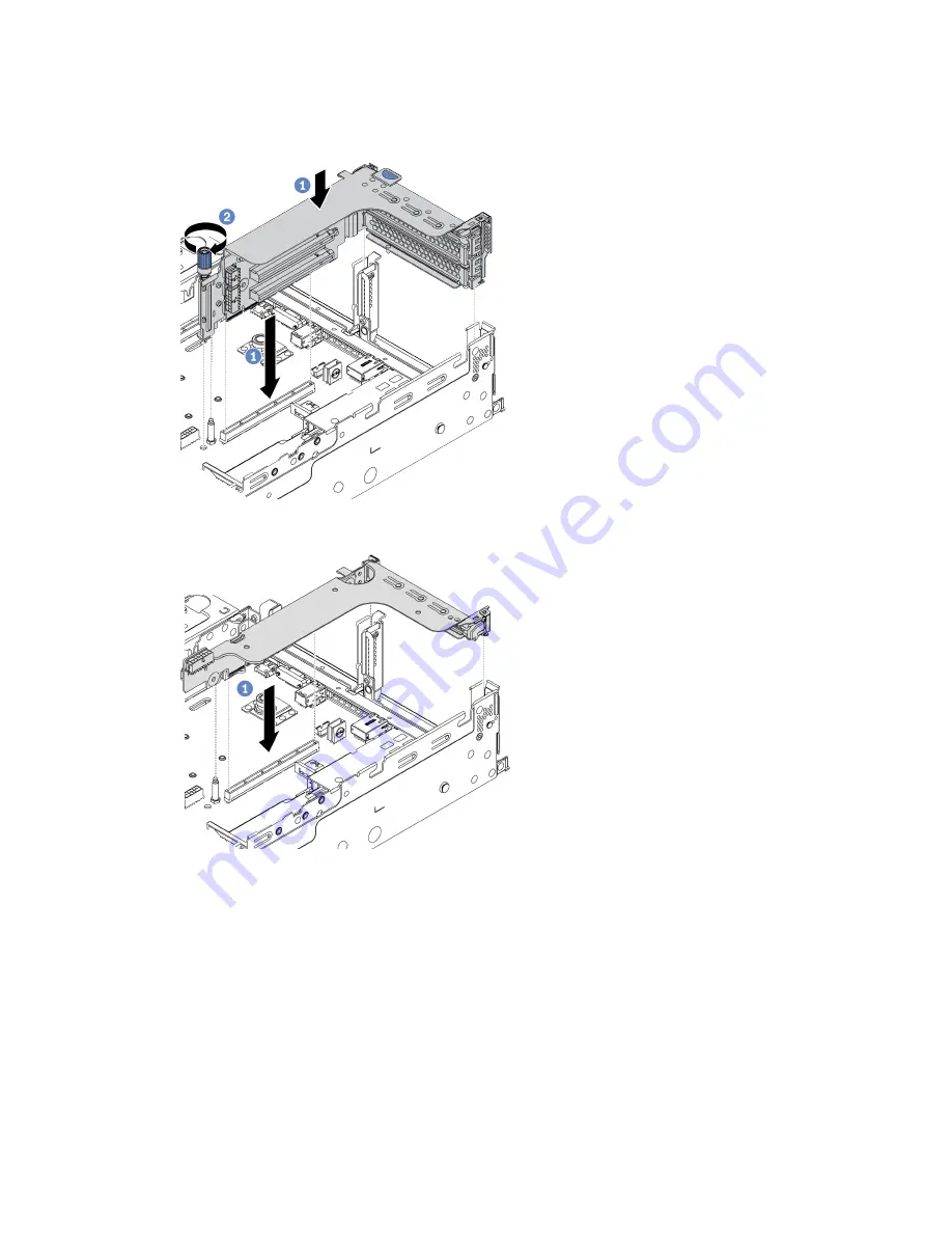
Step 5. Install a riser 1 assembly or riser 2 assembly. The illustration shows installing the riser 1 assemblies.
The procedure is the same for installing riser 2 assemblies.
Figure 93. Riser 1 assembly installation (three-slot bracket)
Figure 94. Riser 1 assembly installation (one-slot riser bracket)
a. Align the riser adapter in the riser cage with the PCIe riser slot on the system board. Carefully
press the PCIe adapter straight into the slot until it is securely seated and its bracket also is
secured.
b. (Optional) If there is one screw on the riser cage, tighten the screw.
After you finish
Refer to Chapter 3 “Internal cable routing” on page 61 to connect any cables to the PCIe adapters.
207
Summary of Contents for ThinkSystem SR665
Page 1: ...ThinkSystem SR665 Setup Guide Machine Types 7D2V and 7D2W ...
Page 20: ...16 ThinkSystem SR665 Setup Guide ...
Page 64: ...60 ThinkSystem SR665 Setup Guide ...
Page 80: ...Figure 24 Cable routing for configuration 4 76 ThinkSystem SR665 Setup Guide ...
Page 121: ...Figure 39 Cable routing for configuration 1 Chapter 3 Internal cable routing 117 ...
Page 124: ...Figure 41 Cable routing for configuration 2 120 ThinkSystem SR665 Setup Guide ...
Page 129: ...Figure 44 Cable routing for configuration 6 Chapter 3 Internal cable routing 125 ...
Page 131: ...Chapter 3 Internal cable routing 127 ...
Page 146: ...142 ThinkSystem SR665 Setup Guide ...
Page 220: ...On GPU air baffle 216 ThinkSystem SR665 Setup Guide ...
Page 240: ...236 ThinkSystem SR665 Setup Guide ...
Page 248: ...244 ThinkSystem SR665 Setup Guide ...
Page 253: ... Copyright Lenovo 2020 249 ...
Page 256: ...252 ThinkSystem SR665 Setup Guide ...
Page 266: ...262 ThinkSystem SR665 Setup Guide ...
Page 267: ......
Page 268: ......


