


7. Install the screw to secure the card reader bracket to the chassis.
Figure 63. Installing the screw that secures the card reader
8. Connect the card reader cable to one of the USB connectors on the system board. See “Locating
parts on the system board” on page 84.
9. Pivot the optical drive bay downward until it snaps into position.
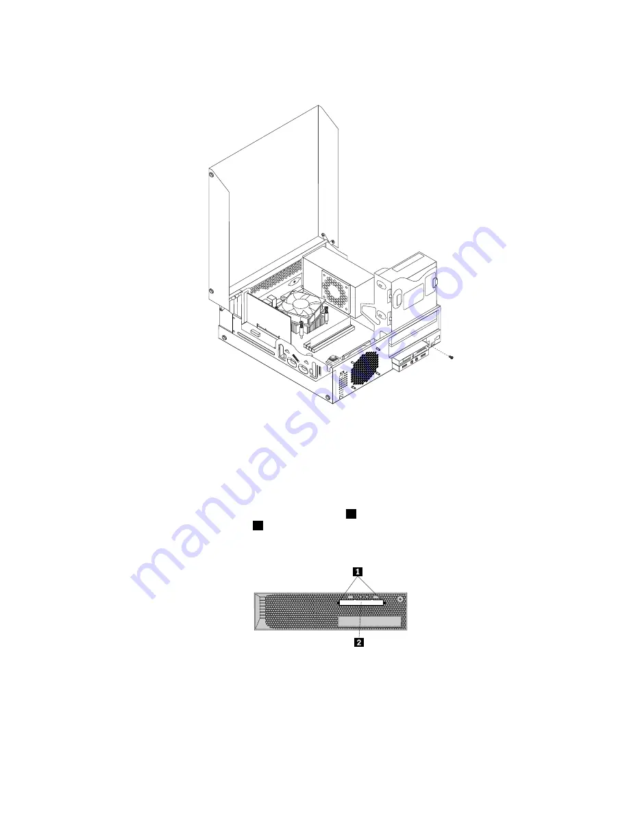
10. Reinstall the front bezel. See “Removing and reinstalling the front bezel” on page 122.
Note:
You might have to remove the card reader cover
2
from the front bezel. To remove the card read
cover, pivot the two retaining clips
1
that secure the card reader cover outwards and then completely
disengage the card reader cover from the front bezel.
Figure 64. Removing the card reader cover
What to do next:
• To work with another piece of hardware, go to the appropriate section.
• To complete the installation or replacement, go to “Completing the parts replacement” on page 167.
Chapter 11
.
Replacing FRUs (for machine types: 3688, 3690, 3691, 3693, and 3695)
131
Summary of Contents for ThinkStation 2551
Page 2: ......
Page 8: ...2 ThinkStation Hardware Maintenance Manual ...
Page 15: ...1 2 Chapter 2 Safety information 9 ...
Page 16: ... 18 kg 37 lbs 32 kg 70 5 lbs 55 kg 121 2 lbs 10 ThinkStation Hardware Maintenance Manual ...
Page 19: ...1 2 Chapter 2 Safety information 13 ...
Page 20: ...1 2 14 ThinkStation Hardware Maintenance Manual ...
Page 21: ...Chapter 2 Safety information 15 ...
Page 27: ...Chapter 2 Safety information 21 ...
Page 31: ...Chapter 2 Safety information 25 ...
Page 60: ...54 ThinkStation Hardware Maintenance Manual ...
Page 70: ...64 ThinkStation Hardware Maintenance Manual ...
Page 186: ...180 ThinkStation Hardware Maintenance Manual ...
Page 187: ......
Page 188: ......