background image

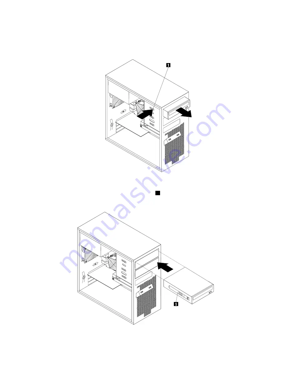
• If you are replacing an optical drive, disconnect the signal cable and the power cable from the rear

of the optical drive, press the blue release button and then slide the optical drive out of the front of
the server.

Figure 14. Removing the optical drive

5. Slide the new optical drive with the optical drive retainer

1

installed into the drive bay from the front of

the server until the optical drive snaps into position.

Figure 15. Installing the optical drive

40

ThinkServer TS130 Hardware Maintenance Manual

Summary of Contents for ThinkSERVER TS130

Page 1: ...ThinkServer TS130 Hardware Maintenance Manual Machine Types 1098 1100 1105 and 1106 ...

Page 2: ...anty and Support Information document on the documentation DVD Third Edition February 2012 Copyright Lenovo 2011 2012 LIMITED AND RESTRICTED RIGHTS NOTICE If data or software is delivered pursuant a General Services Administration GSA contract use reproduction or disclosure is subject to restrictions set forth in Contract No GS 35F 05925 ...

Page 3: ...lling or replacing the optical drive 39 Replacing the primary hard disk drive 41 Installing or replacing the secondary hard disk drive 44 Installing removing or replacing hardware devices 47 Replacing the power supply assembly 48 Replacing the heat sink and fan assembly 50 Replacing the front audio and USB assembly 52 Replacing the front fan assembly 53 Replacing the rear fan assembly 55 Replacing...

Page 4: ...106 Appendix C Notices 107 Trademarks 108 Important notes 108 Polyvinyl Chloride PVC cable and cord notice 108 Recycling information 108 Battery return program 109 Requirement for batteries containing perchlorate 110 Particulate contamination 111 Important information for the European Directive 2002 96 EC 111 Restriction of Hazardous Substances Directive RoHS 115 China RoHS 115 Turkish statement o...

Page 5: ...ice and assistance see the Warranty and Support Information document Safety information Note Before using the product be sure to read and understand the multilingual safety instructions on the documentation DVD that comes with the product Antes de usar o produto leia e entenda as instruções de segurança multilíngues no DVD de documentação que o acompanha Преди да използвате този продукт задължител...

Page 6: ...ente as instruções de segurança multilingues que constam no DVD de documentação fornecido com o produto Înainte de a utiliza produsul asiguraţi vă că aţi citit şi înţeles instrucţiunile de siguranţă în mai multe limbi de pe DVD ul cu documentaţie care însoţeşte produsul Før du bruker produktet må du lese og forstå den flerspråklige sikkerhetsinformasjonen på DVDen med dokumentasjon som følger med ...

Page 7: ...tatement 1 DANGER Electrical current from power telephone and communication cables is hazardous To avoid a shock hazard Do not connect or disconnect any cables or perform installation maintenance or reconfiguration of this product during an electrical storm Connect all power cords to a properly wired and grounded electrical outlet Connect to properly wired outlets any equipment that will be attach...

Page 8: ...such as CD ROMs DVD drives fiber optic devices or transmitters are installed note the following Do not remove the covers Removing the covers of the laser product could result in exposure to hazardous laser radiation There are no serviceable parts inside the device Use of controls or adjustments or performance of procedures other than those specified herein might result in hazardous radiation expos...

Page 9: ...To remove all electrical current from the device ensure that all power cords are disconnected from the power source Statement 6 CAUTION If you install a strain relief bracket option over the end of the power cord that is connected to the device you must connect the other end of the power cord to an easily accessible power source Statement 7 CAUTION If the device has doors be sure to remove or secu...

Page 10: ... the hot swap fan cables before removing the fan from the device Statement 10 CAUTION The following label indicates sharp edges corners or joints nearby Statement 11 CAUTION The following label indicates a hot surface nearby Statement 12 DANGER Overloading a branch circuit is potentially a fire hazard and a shock hazard under certain conditions To avoid these hazards ensure that your system electr...

Page 11: ...uipment must be installed by trained service personnel in a restricted access location as defined by the NEC and the latest edition of IEC 60950 The Standard for Safety of Information Technology Equipment Connect the equipment to a reliably grounded safety extra low voltage SELV source An SELV source is a secondary circuit that is designed so that normal and single fault conditions do not cause th...

Page 12: ...parts Keep fingers and other body parts away Statement 20 CAUTION The battery is a lithium ion battery To avoid possible explosion do not burn the battery Exchange it only with the Lenovo approved part Recycle or discard the battery as instructed by local regulations 8 ThinkServer TS130 Hardware Maintenance Manual ...

Page 13: ...rated graphics for a Video Graphics Array VGA connector and a DisplayPort connector Connectivity 100 1000 Mbps integrated Ethernet controller Power supply Your server comes with one of the following power supplies 280 watt auto sensing power supply 320 watt auto sensing power supply Expansion Two optical drive bays Two hard disk drive bays Two PCI card slots One PCI Express x1 card slot One PCI Ex...

Page 14: ...um 180 V ac Maximum 264 V ac Environment Air temperature Operating 10 C to 35 C 50 F to 95 F Non operating 40 C to 60 C 14 F to 140 F with package Non operating 10 C to 60 C 14 F to 140 F without package Humidity Operating 10 to 80 non condensing 10 per hour Non operating 10 to 90 non condensing 10 per hour Altitude Operating 50 to 10 000 ft 15 2 to 3 048 m Non operating 50 to 35 000 ft 15 2 to 10...

Page 15: ...dvanced Desktop Management Interface DMI Automatic memory downsizing on error detection Automatic restart on non maskable interrupt NMI Availability of microcode level Built in menu driven setup system configuration and RAID configuration Built in monitoring for fan temperature and voltage Cooling fans with speed sensing capability ECC DDR3 SDRAM with Serial Presence Detect SPD Error codes and mes...

Page 16: ...12 ThinkServer TS130 Hardware Maintenance Manual ...

Page 17: ...ear of the server and to a working electrical outlet If your server has a secondary power switch on the rear of the server make sure that it is switched on The power indicator on the front of the server is on The server voltage matches the voltage available at the electrical outlet for your country or region The monitor screen is blank Verify that The monitor signal cable is correctly connected to...

Page 18: ...t drive Install an operating system on the boot drive The boot sector on the startup drive is corrupted The drive must be formatted Do the following 1 Attempt to back up the data on the failing hard disk drive 2 Using the operating system programs format the hard disk drive The drive is defective Replace the hard disk drive Power supply problems If you suspect a power supply problem use the follow...

Page 19: ...es When you correct the cause of the first error message probably the other error messages will not be displayed the next time you turn on the computer POST error code POST error message Description Action 00CE Machine Type or Serial Number is INVALID This error message is displayed when the machine type or the serial number is invalid 0210 Stuck key This error message is displayed when a key is k...

Page 20: ...urity data corrupted Press F1 to enter the Setup Utility program Then press F10 to save the operation and exit the Setup Utility program 0176 System security The system has been tampered with This error message is displayed when the computer is turned on with the cover open or removed Press F1 to enter the Setup Utility program Then press F10 to save the operation and exit the Setup Utility progra...

Page 21: ...ram Miscellaneous error messages Symptom FRU Action Changing display colors Display Monitor Computer will not turn off See Hard disk drive boot error on page 14 1 Power switch 2 System board 3 Riser card if installed Computer will not RPL from server 1 Ensure that Network is set as the first device or it is after CD DVD in the startup sequence 2 Ensure that the network adapter is enabled for RPL 3...

Page 22: ...dministrator is using the LCCM Hybrid RPL check startup sequence a First device Network b Second device Hard disk drive 2 Check the hard disk drive RPL computer does not RPL from server 1 Check the startup sequence 2 Check the network adapter LED status Serial or parallel port device failure system board port 1 Run an external device self test 2 Check the external device 3 Check the cable 4 Check ...

Page 23: ...cache f External cache RAM g Hard disk drive h Diskette drive 3 Turn on the server to re test the system 4 Repeat steps 1 through 3 until you find the failing components If all devices and adapters have been removed and the problem continues replace the system board Chapter 3 Diagnostics and troubleshooting 19 ...

Page 24: ...20 ThinkServer TS130 Hardware Maintenance Manual ...

Page 25: ...and connector locations on page 21 shows the locations of the controls and connectors on the front of your server Figure 1 Front control and connector locations 1 Optical drive eject close button 4 Power switch 2 Hard disk drive activity LED 5 USB connectors 2 3 Power on LED Front control panel LEDs The following table describes the meaning of the LEDs on the front control panel Copyright Lenovo 2...

Page 26: ... drive is active Rear view Figure 2 Rear connector locations on page 22 shows the locations of the connectors on the rear of your server Some connectors on the rear of your server are color coded to help you determine where to connect the cables in your server Figure 2 Rear connector locations 1 Power cord connector 7 Microphone connector 2 Serial port 8 Audio line out connector 3 VGA monitor conn...

Page 27: ...that use a DisplayPort connector Ethernet connector Used to attach an Ethernet cable for a local area network LAN Note To operate the server within FCC Class B limits use a Category 5 Ethernet cable Microphone connector Used to attach a microphone to your server when you want to record sound or if you use speech recognition software Serial port Used to attach an external modem a serial printer or ...

Page 28: ...mplementary Metal Oxide Semiconductor Recovery jumper 5 Memory slot 3 DIMM3 18 Internal speaker connector 6 Memory slot 4 DIMM4 19 Front audio connector for connecting the microphone and headphone connectors on the front bezel 7 Thermal sensor connector 20 PCI card slots 2 8 24 pin power connector 21 PCI Express x1 card slot 9 Battery 22 PCI Express x16 graphics card slot 10 SATA connectors 1 and ...

Page 29: ...de of the server see Removing the server cover on page 31 Figure 4 Component locations 1 Heat sink 7 Secondary hard disk drive installed in some models 2 Microprocessor 8 Primary hard disk drive 3 Memory modules 9 System board 4 Optical drive 10 Rear fan assembly 5 Front bezel 11 Power supply 6 Front fan assembly Chapter 4 Locating parts controls LEDs and connectors 25 ...

Page 30: ...26 ThinkServer TS130 Hardware Maintenance Manual ...

Page 31: ...ll optional hardware devices make sure that the server is working correctly If an operating system is installed turn on the server and make sure that the operating system starts If no operating system is installed make sure that a 19990305 error code is displayed indicating that an operating system was not found but the server is working correctly If the server is not working correctly refer to th...

Page 32: ...he server is running Operating the server without the air duct or air baffles might cause the microprocessor to overheat The second microprocessor socket always contains either a microprocessor socket cover or a microprocessor and heat sink Handling static sensitive devices Attention Do not open the static protective package containing the new part until the defective part has been removed from th...

Page 33: ...se the information in this section to help you identify potential unsafe conditions in a Lenovo product that you are working on Each Lenovo product as it was designed and manufactured has required safety items to protect users and service technicians from injury The information in this section addresses only those items Use good judgment to identify potential unsafe conditions that might be caused...

Page 34: ...ncy power off EPO switch disconnecting switch or electrical outlet so that you can turn off the power quickly in the event of an electrical accident Disconnect all power before you perform a mechanical inspection work near power supplies or remove or install main units Before you work on the equipment disconnect the power cord If you cannot disconnect the power cord have the customer power off the...

Page 35: ...rver cover To remove the server cover do the following 1 Remove any media from the drives and turn off all attached devices and the server 2 Disconnect all power cords from electrical outlets 3 Disconnect the power cords Input Output I O cables and any other cables that are connected to the server See Front view on page 21 and Rear view on page 22 4 Remove any locking device that secures the serve...

Page 36: ...ions on how to remove and reinstall the front bezel To remove and reinstall the front bezel do the following 1 Remove all media from the drives and turn off all attached devices and the server Then disconnect all power cords from electrical outlets and disconnect all cables that are connected to the server 2 Remove the server cover See Removing the server cover on page 31 3 Remove the front bezel ...

Page 37: ...server by adding memory modules PCI cards or drives and maintain your server by replacing the failing optional hardware devices If you are replacing an optional hardware device perform the removal procedure and then perform the installation procedure for the optional hardware device that you want to replace Installing or replacing a PCI card Attention Do not open your server or attempt any repair ...

Page 38: ...sconnect all power cords from electrical outlets and disconnect all cables that are connected to the server 2 Remove the server cover See Removing the server cover on page 31 3 At the rear of the server press the release button 1 to open the PCI card latch 2 Figure 8 Opening the PCI card latch 34 ThinkServer TS130 Hardware Maintenance Manual ...

Page 39: ...lot b If the PCI card is held in place by a retaining latch press the card retaining latch 1 as shown to disengage the latch Grasp the PCI card and gently pull it out of the card slot Figure 9 Removing a PCI card 5 Remove the new PCI card from its static protective package 6 Install the new PCI card into the appropriate slot on the system board See Locating parts on the system board on page 24 Not...

Page 40: ...ard Use any documentation that came with the Ethernet card and follow those instructions in addition to the instructions in this section To install or remove the Ethernet card do the following 1 Remove all media from the drives and turn off all attached devices and the server Then disconnect all power cords from electrical outlets and disconnect all cables that are connected to the server 2 Remove...

Page 41: ...umentation DVD that came with your product and Guidelines on page 27 To obtain a copy of the publications go to http support lenovo com This section provides instructions on how to install or remove a memory module Your server has four slots for installing or replacing DDR3 UDIMMs that provide up to a maximum of 16 GB system memory When installing or replacing a memory module use the following gui...

Page 42: ...a new memory module open the retaining clips of the memory slot into which you want to install the memory module Figure 12 Opening the retaining clips 7 Touch the static protective package that contains the new memory module to any unpainted metal surface on the outside of the server Then remove the new memory module from the package 38 ThinkServer TS130 Hardware Maintenance Manual ...

Page 43: ...any repair before reading and understanding the Safety Information and the Warranty and Support Information on the documentation DVD that came with your product and Guidelines on page 27 To obtain a copy of the publications go to http support lenovo com This section provides instructions on how to install or replace the optical drive To install or replace an optical drive do the following 1 Remove...

Page 44: ...and then slide the optical drive out of the front of the server Figure 14 Removing the optical drive 5 Slide the new optical drive with the optical drive retainer 1 installed into the drive bay from the front of the server until the optical drive snaps into position Figure 15 Installing the optical drive 40 ThinkServer TS130 Hardware Maintenance Manual ...

Page 45: ... repair before reading and understanding the Safety Information and the Warranty and Support Information on the documentation DVD that came with your product and Guidelines on page 27 To obtain a copy of the publications go to http support lenovo com This section provides instructions on how to replace the primary hard disk drive To replace the primary hard disk drive do the following 1 Remove all...

Page 46: ...e from the bracket 7 To install a new hard disk drive into the blue bracket flex the sides of the bracket and align pin 1 pin 2 pin 3 and pin 4 on the bracket with the corresponding holes in the hard disk drive Do not touch the circuit board 5 on the bottom of the hard disk drive Note If you are installing a 2 5 inch hard disk drive install the hard disk drive into a 2 5 inch to 3 5 inch hard disk...

Page 47: ...age into the chassis Press down on the metal latch 2 and pivot the hard disk drive cage into place Then slide the drive cage to the front of the server until it snaps into position Note There are two arrows one on the upper drive cage and one on the hard disk drive cage The arrows are aligned when the hard disk drive is in the correct position Figure 19 Installing the primary hard disk drive Chapt...

Page 48: ...Information and the Warranty and Support Information on the documentation DVD that came with your product and Guidelines on page 27 To obtain a copy of the publications go to http support lenovo com To install or replace the secondary hard disk drive do the following 1 Remove all media from the drives and turn off all attached devices and the server Then disconnect all power cords from electrical ...

Page 49: ...m the bracket 8 To install the secondary hard disk drive flex the sides of the bracket properly and align pin 1 pin 2 pin 3 and pin 4 on the bracket with the corresponding holes in the hard disk drive Do not touch the circuit board 5 on the bottom of the hard disk drive Note If you are installing a 2 5 inch hard disk drive install the hard disk drive into a 2 5 inch to 3 5 inch hard disk drive tra...

Page 50: ...ard disk drive cage until it snaps into position 10 Slide the hard disk drive cage with the new hard disk drive into the chassis until it is directly underneath the metal tab 1 Figure 23 Installing the secondary hard disk drive 46 ThinkServer TS130 Hardware Maintenance Manual ...

Page 51: ... on page 24 Then locate an available five wire power connector and connect it to the hard disk drive Figure 25 Connecting a SATA hard disk drive Installing removing or replacing hardware devices This section provides instructions on how to install remove or replace hardware devices for your server You can maintain your server by replacing the failing hardware devices If you are replacing a hardwar...

Page 52: ...s away CAUTION Never remove the cover on a power supply or any part that has the following label attached Hazardous voltage current and energy levels are present inside any component that has this label attached There are no serviceable parts inside these components If you suspect a problem with one of these parts contact a service technician To replace the power supply assembly do the following 1...

Page 53: ... new power supply assembly is the correct replacement 7 Install the new power supply assembly into the chassis so that the screw holes in the power supply assembly align with those in the chassis 8 Install and tighten the four screws to secure the power supply assembly Note Use only screws provided by Lenovo 9 Reconnect the power supply assembly cables to the system board and each of the drives 10...

Page 54: ... Turn off the server and wait three to five minutes to let the server cool before removing the server cover To replace the heat sink and fan assembly do the following 1 Remove all media from the drives and turn off all attached devices and the server Then disconnect all power cords from electrical outlets and disconnect all cables that are connected to the server 2 Remove the server cover See Remo...

Page 55: ...new heat sink and fan assembly on the system board so that the four screws on the heat sink and fan assembly are aligned with the corresponding holes on the system board Make sure that you properly place the heat sink and fan assembly so that you can easily connect the heat sink and fan assembly cable to the microprocessor fan connector on the system board 9 Follow this sequence to install the fou...

Page 56: ...ver See Removing the server cover on page 31 3 Remove the front bezel See Removing and reinstalling the front bezel on page 32 4 Disconnect the front audio and USB assembly cable from the system board See Locating parts on the system board on page 24 5 Note the front audio and USB assembly cable routing and remove the screw that secures the front audio and USB assembly Then remove the front audio ...

Page 57: ...ction provides instructions on how to replace the front fan assembly To replace the front fan assembly do the following 1 Remove all media from the drives and turn off all attached devices and the server Then disconnect all power cords from electrical outlets and disconnect all cables that are connected to the server 2 Remove the server cover See Removing the server cover on page 31 3 Remove the f...

Page 58: ...bs 1 that attach the front fan assembly to the chassis as shown and then completely remove the front fan assembly from the chassis Figure 30 Removing the front fan assembly 54 ThinkServer TS130 Hardware Maintenance Manual ...

Page 59: ...e parts replacement on page 64 Replacing the rear fan assembly Attention Do not open your server or attempt any repair before reading and understanding the Safety Information and the Warranty and Support Information on the documentation DVD that came with your product and Guidelines on page 27 To obtain a copy of the publications go to http support lenovo com This section provides instructions on ...

Page 60: ...embly is attached to the chassis by four rubber mounts Remove the rear fan assembly by cutting the rubber mounts and gently pulling the rear fan assembly out of the chassis Figure 32 Removing the rear fan assembly 6 Install the new rear fan assembly by aligning the new rubber mounts with the corresponding holes in the chassis and push the rubber mounts through the holes Note The new rear fan assem...

Page 61: ...s replacement on page 64 Replacing the microprocessor Attention Do not open your server or attempt any repair before reading and understanding the Safety Information and the Warranty and Support Information on the documentation DVD that came with your product and Guidelines on page 27 To obtain a copy of the publications go to http support lenovo com This section provides instructions on how to re...

Page 62: ... disconnect all cables connected to the system board See Locating parts on the system board on page 24 5 Remove the heat sink and fan assembly See Replacing the heat sink and fan assembly on page 50 Note Place the heat sink and fan assembly on its side so that the thermal grease on the bottom of it does not get in contact with anything 6 Lift the small handle 1 and open the retainer 2 to access th...

Page 63: ...Make sure that the small handle is in the raised position and the microprocessor retainer is fully open 9 Remove the protective cover that protects the gold contacts of the new microprocessor 10 Hold the new microprocessor by its sides and align the small triangle on one corner of the new microprocessor with the corresponding small triangle on one corner of the microprocessor socket 11 Lower the n...

Page 64: ...e server Be sure to consider the following information when you replace the battery in the server You must replace the battery with a lithium battery of the same type from the same manufacturer To avoid possible danger be sure to read and understand the following safety statement After you replace the system board battery you must reset passwords system date and time and reconfigure the server Sta...

Page 65: ...he failing battery as required by local ordinances or regulations What to do next To work with another piece of hardware go to the appropriate section To complete the replacement go to Completing the parts replacement on page 64 Replacing the system board Attention Do not open your server or attempt any repair before reading and understanding the Safety Information and the Warranty and Support Inf...

Page 66: ...ing the system board battery on page 60 8 Remove the front fan assembly from the computer See Replacing the front fan assembly on page 53 9 Note the location of all cable connections on the system board and disconnect all cables See Locating parts on the system board on page 24 10 Remove the eight screws that secure the system board to the chassis by following the sequence shown in the following i...

Page 67: ...rocessor on the sides and lift it straight up and out of the socket Do not touch the contacts on the microprocessor socket 3 Align the notches 1 of the microprocessor socket cover with the alignment keys 2 of the microprocessor socket Lower the socket cover straight down into the microprocessor socket on the system board Note Your microprocessor socket and cover might look slightly different from ...

Page 68: ...ce with reinstalling the server cover 4 Position the server cover on the chassis so that the rail guides on the bottom of the server cover engage the rails on the chassis Then slide the cover to the front of the server until it snaps into position Figure 39 Reinstalling the server cover 5 Install the screws to secure the server cover 6 Lock the server cover if you have a server cover lock 7 Reconn...

Page 69: ...er While the server remains connected to ac power one or more fans might continue to run To remove all power from the server you must disconnect it from the power source Some operating systems require an orderly shutdown before you turn off the server See your operating system documentation for information about shutting down the operating system Statement 5 CAUTION The power control button on the...

Page 70: ...l attached devices 3 Follow the instructions that come with the device to prepare it for installation and to connect it to the server Updating the server configuration When you start the server for the first time after you install or remove an internal option or external device you might receive a message saying that the configuration has changed The Setup Utility program starts automatically so t...

Page 71: ...acement of self service CRUs is your responsibility If Lenovo installs a self service CRU at your request you will be charged for the installation Optional service customer replaceable unit You may install an optional service CRU yourself or request Lenovo to install it at no additional charge under the type of warranty service that is designated for your server Field replaceable unit FRU FRUs mus...

Page 72: ...els CTO 12U 12F 12M 12J 12S 12L 12D 12Y 03X3764 1 7 Hard disk drive non hot swap 500 GB SATA Enterprise 7200 rpm 3 GB s XX MB cache 3 5 drive assembly models CTO 03X3765 1 7 Hard disk drive non hot swap 1 TB SATA Enterprise 7200 rpm 3 GB s XX MB cache 3 5 drive assembly models CTO 03X3767 1 7 Hard disk drive non hot swap 2 TB SATA Enterprise 7200 rpm 3 GB s XX MB cache 3 5 drive assembly models CT...

Page 73: ...Microprocessor Core i3 2120 dual core 1 GT 3 3 GHz 65 W models CTO 03T8010 N 3 Memory modules DDR3 ECC PC3 10600 2 GB UDIMM 1333 models CTO 12U 12F 12G 12M 12J 12S 12L 12D 12Y 03X3660 1 3 Memory modules DDR3 ECC PC3 10600 4 GB UDIMM 1333 models CTO 03X3661 1 4 Optical drive DVD ROM drive 16x 48x SATA models CTO 12U 12F 12G 12M 12J 12S 12L 12D 12Y 71Y5543 1 4 Optical drive DVD Burner CD RW Rambo 8 ...

Page 74: ...J9495 1 Lenovo RDX 160 GB internal USB drive models CTO 03X3662 1 Lenovo RDX 320 GB internal USB drive models CTO 03X3663 1 Lenovo RDX 500 GB internal USB drive models CTO 03X3664 1 Table 6 Parts listing type 1105 Item 1105 FRUs FRU CRU 1 Thermal kit 95 and 73 W including heatsink RM and mounting plate models CTO all models 03X3844 1 2 Microprocessor E3 1275 quad core 2 GT 3 40 GHz 95 W models CTO...

Page 75: ... board CPA SX31200 V1 0 TPM enabled models CTO 15U 15F 15M 15J 15S 15L 15D 15Y 16J 18U 18F 18M 18J 18S 18L 18D 18Y 19U 19F 19M 19J 19S 19L 19D 19Y 1AU 1AF 1AM 1AJ 1AS 1AL 1AD 1AY 1BU 1BF 1BM 1BJ 1BS 1BL 1BD 1BY 1CU 1CF 1CM 1CJ 1CS 1CL 1CD 1CY 1DU 1DF 1DM 1DJ 1DS 1DL 1DD 1DY 1EU 1EF 1EM 1EJ 1ES 1EL 1ED 1EY 11G A1G A1J 03T8003 N 8 System board CPA SX31200 V1 0 TPM disabled surge protection models CT...

Page 76: ...1 GHz 65 W models CTO A3U A3F A3S A3P A3L A3D A3Y A3G A3M A3J 03T8011 N 2 Microprocessor Core i3 2120 dual core 1 GT 3 3 GHz 65 W models CTO 1EU 1EF 1EM 1EJ 1ES 1EL 1ED 1EY 1EG 03T8010 N 3 Memory modules DDR3 ECC PC3 10600 2 GB UDIMM 1333 models CTO 1EU 1EF 1EM 1EJ 1ES 1EL 1ED 1EY 1EG A2U A2F A2S A2P A2L A2D A2Y A2G A2M A2J A3U A3F A3S A3P A3L A3D A3Y A3G A3M A3J 03X3660 1 3 Memory modules DDR3 EC...

Page 77: ... CTO all models 41R6106 2 Cable SATA 120 mm RoHS models CTO all models 41R3328 1 Cable PATA 1 2 for RDX models CTO all models 03X3759 1 Cable SATA 250 mm 1 latching for device RoHS models CTO all models 54Y9929 1 Optical drive 15 u 750 mm single SATA cable V1 0 models CTO 03X3696 1 Intel Pro 1000 PT dual port Ethernet card models CTO 67Y1430 1 NVIDIA graphics card NVS300 512 MB DMS59 models CTO 03...

Page 78: ...nadian Standards Association CSA For units intended to be operated at 115 volts Use a UL listed and CSA certified cord set consisting of a minimum 18 AWG Type SVT or SJT three conductor cord a maximum of 15 feet in length and a parallel blade grounding type attachment plug rated 15 amperes 125 volts For units intended to be operated at 230 volts U S use Use a UL listed and CSA certified cord set c...

Page 79: ...Line cord US models CTO 12U 12F 12D 12S 12L 41R3184 1 Line cord China models CTO 41R3256 1 Line cord Japan models CTO 12J 24R2633 1 Line cord Brazil models CTO 45J9595 1 Line cord Latin America High Voltage Argentina Paraguay Uruguay models CTO 12Y 12L 41R3176 1 Line cord Australia New Zealand models CTO 12M 41R3196 1 Line cord Korea models CTO 41R3260 1 Line cord Hong Kong United Kingdom Singapor...

Page 80: ...e cord India models CTO 41R3341 1 Table 15 Secondary power cords type 1100 1100 Secondary power cords FRU CRU Line cord US models CTO 12U 12F 12D 12S 12L 41R3184 1 Line cord China models CTO 41R3256 1 Line cord Japan models CTO 12J 24R2633 1 Line cord Brazil models CTO 45J9595 1 Line cord Latin America High Voltage Argentina Paraguay Uruguay models CTO 12Y 12L 41R3176 1 Line cord Australia New Zea...

Page 81: ...Portugal Romania Spain Sweden models CTO 11G A1G 41R3208 1 Line cord Denmark models CTO 11G A1G 41R3212 1 Line cord Switzerland models CTO 11G A1G 41R3228 1 Line cord Israel CTO 11G A1G 41R3236 1 Line cord South Africa models CTO 15M 18M 19M 1AM 1BM 1CM 1DM 1EM 11G A1G 41R3220 1 Line cord India models CTO 41R3341 1 Table 17 Secondary power cords type 1105 1105 Secondary power cords FRU CRU Line co...

Page 82: ...ealand models CTO 1EM A1M A2M A3M 41R3196 1 Line cord Korea models CTO 41R3260 1 Line cord Hong Kong United Kingdom Singapore Malaysia Brunei Ireland models CTO 1GG 1HG A1G 1EG A2G A3G 41R3224 1 Line cord Taiwan models CTO 41R3278 1 Line cord Italy models CTO 1GG 1HG A1G 1ES 1EL 1EY 1EG A2G A2S A2L A2Y A3G A3S A3L A3Y 41R3232 1 Line cord Indonesia Laos Cambodia Vietnam Austria Belgium Croatia Czec...

Page 83: ... 41R3278 1 Line cord Italy models CTO 1GG 1HG A1G 1ES 1EL 1EY 1EG A2G A2S A2L A2Y A3G A3S A3L A3Y 41R3232 1 Line cord Indonesia Laos Cambodia Vietnam Austria Belgium Croatia Czechoslovakia Finland France Germany Hungary Netherlands Norway Poland Portugal Romania Spain Sweden models CTO 41R3208 1 Line cord Denmark models CTO 1GG 1HG A1G 1EG A2G A3G 41R3212 1 Line cord Switzerland models CTO 1GG 1HG...

Page 84: ...80 ThinkServer TS130 Hardware Maintenance Manual ...

Page 85: ...go screen release the F1 key Note If a Power On Password or an Administrator Password has been set the Setup Utility program menu will not be displayed until you type the correct password For more information see Using passwords on page 94 When the POST detects that the hard disk drive has been removed from your computer or the memory module size has decreased an error message will be displayed wh...

Page 86: ...curity Set the security parameters See Table 37 Items under the Security menu on page 90 Startup From the currently detected boot devices select the first boot device for system initialization See Table 42 Items under the Startup menu on page 93 Exit Exit the Setup Utility program See Table 43 Items under the Exit menu on page 94 Table 21 Items under the Main menu Item Option or description System...

Page 87: ...the system time System Date MM DD YYYY MM DD YYYY Set the system date Table 24 Items under the Devices menu Item Description Serial Port Setup Enter the submenu to view all the options See Table 25 Submenus under the Serial Port Setup menu on page 84 USB Setup Enter the submenu to view all the options See Table 26 Submenus under the USB Setup menu on page 84 ATA Drive Setup Enter the submenu to vi...

Page 88: ...led Enable or disable USB port 2 USB Port 3 Enabled Disabled Enable or disable USB port 3 USB Port 4 Enabled Disabled Enable or disable USB port 4 USB Port 5 Enabled Disabled Enable or disable USB port 5 USB Port 6 Enabled Disabled Enable or disable USB port 6 USB Port 7 Enabled Disabled Enable or disable USB port 7 USB Port 8 Enabled Disabled Enable or disable USB port 8 Note indicates the defaul...

Page 89: ...e following sequence PEG PCI e Graphics Device PCI PCI Graphics Device and IGD Internal Graphics Device Notes When you select IGD the following items will be hidden Pre Allocated Memory Size Total Graphics Memory Multi Monitor Support Pre Allocated Memory Size 32 MB 64 MB 128 MB Memory allocated to IGD Total Graphics Memory 128MB 256 MB Maximum Total memory allocated to graphics devices Note This ...

Page 90: ...ending on the type of the microprocessor Table 32 Submenus under the CPU Setup menu Item Option Description Intel SpeedStep Technology Enabled Disabled Enable or disable the Intel SpeedStep technology This technology enables the system to dynamically adjust processor voltage and core frequency which can result in decreased average power consumption and decreased average heat production Core Multi ...

Page 91: ... Technology This technology provides hardware based mechanisms that help protect against software based attacks and protect the confidentiality and integrity of data stored or created on client computers This setting might impact system performance Note If TxT is set to Enabled the TCG security feature will be set to Active automatically C State Support C1 C1C3 C1C3C6 Select supported CPU power ma...

Page 92: ... The MEBx password will also be reset Press Ctrl P to enter MEBx Enabled Disabled Enable or disable the Press Ctrl P to enter MEBx function This function provides platform level configuration options for you to configure the Management Engine ME platform SOL Configuration Enter the submenu to view all the options See Table 34 Submenus under the SOL Configuration menu on page 88 Notes 1 indicates t...

Page 93: ...the Wake Up on Alarm function is supported The Intel Manageability Management function cannot be used Smart Performance Choice Better Acoustic Performance Better Thermal Performance Enable the system to enter the lower acoustic level or better thermal level Automatic Power On Enter the submenus to view all the options See Table 36 Submenus under the Automatic Power On menu on page 89 Note indicate...

Page 94: ...em is to wake up Alarm Date MM DD YYYY 01 01 1999 Specify the date when the system is to wake up Alarm Day of Week Sunday Monday Tuesday Wednesday Thursday Friday Saturday Select the day of the week when the system is to wake up Note indicates the default setting Table 37 Items under the Security menu Item Option Description Hardware Password Manager Enabled Disabled Current setting Registered Dis...

Page 95: ...nu on page 92 Configuration Change Detection Enabled Disabled Enable or disable Configuration Change Detection Note indicates the default setting Table 38 Submenus under the Hard Disk Password menu Item Option Description SATA Drive 0 Password Disabled User User Master The Hard Disk Password prevents unauthorized users from accessing the data on the hard disk drive In addition to the User Password...

Page 96: ...t data stored in a fingerprint reader Note indicates the default setting Table 40 Submenus under the TCG Feature Setup submenu Item Option Description TCG Security Feature Active Inactive Disabled Change the TCG Security Feature settings Active The feature is fully functional Inactive The feature is visible but is not functional Disabled The feature is hidden and not functional Note When you set i...

Page 97: ...Select Enabled to obtain the fastest boot time Select Disabled to test for a stuck key during the POST and you may hear a beep after POST completes Boot Up Num Lock Status On Off This field indicates the state of the NumLock feature of the keyboard after startup If NumLock is On the keys on the keyboard will act as numeric keys If NumLock is Off the keys on the keyboard will act as cursor keys Key...

Page 98: ...rd Changes and Exit Exit the Setup Utility program without saving any changes Load Optimal Defaults Restore Load default values for all the setup options Viewing and changing settings The Setup Utility program menu lists various items about the system configuration To view or change settings start the Setup Utility program See Starting the Setup Utility program on page 81 Then follow the instructi...

Page 99: ...cannot be accessed until a valid password is typed in If both the Power On Password and Administrator Password are set you can type either password However you must use your Administrator Password to change any configuration settings Hard Disk Password Setting a Hard Disk Password prevents unauthorized access to the data on the hard disk drive When a Hard Disk Password is set you are prompted to t...

Page 100: ...proximately five seconds 9 Repeat step 1 through step 4 10 Move the Clear CMOS Recovery jumper back to the standard position pin 1 and pin 2 11 Reinstall all parts and reconnect all cables that have been removed 12 Reinstall the server cover and connect the power cords See Completing the parts replacement on page 64 Enabling or disabling a device This section provides information on how to enable ...

Page 101: ... Error Startup Sequence Read the information displayed on the right side of the screen 4 Press F10 to save changes and exit the Setup Utility program See Exiting from the Setup Utility program on page 97 Exiting from the Setup Utility program After you finish viewing or changing settings press Esc to return to the Setup Utility program main menu You might have to press Esc several times Do one of ...

Page 102: ... Create RAID Volume and press Enter 3 Type a proper RAID volume name in the Name field and press Tab 4 Use the arrow keys to select a RAID level in the RAID Level field and press Tab 5 If appropriate use the arrow keys to select a stripe size in the Stripe Size field and press Tab 6 Type a volume size in the Capacity field and press Tab 7 Press Enter to initiate volume creation 8 When prompted pre...

Page 103: ...as the BIOS ROM file and RAID FW files When you replace a device in the server you might have to either update the server with the latest version of the firmware that is stored in memory on the device or restore the pre existing firmware from a diskette or CD image The BIOS ROM file is stored in flash on the system board The onboard SATA software RAID firmware is integrated into the BIOS ROM on th...

Page 104: ...ooting DVD Easy to use language selectable interface Integrated help system Automatic hardware detection RAID configuration utility Device drivers provided based on the server model and detected devices Selectable partition size and file system Support for multiple operating systems Installing the operating system and device drivers in an unattended mode to save time Creating a reuseable response ...

Page 105: ...u do not make this change by pressing N However if you do want to change the serial number press Y then type in the serial number and press Enter 5 When prompted to change the machine type and model it is suggested that you do not make this change by pressing N However if you do want to change the machine type and model press Y then type in the machine type and model and press Enter 6 Follow the i...

Page 106: ...pin 2 and pin 3 6 Reconnect any cables that were disconnected and reinstall the PCI card if removed 7 Reinstall the computer cover and reconnect the power cords for the computer and monitor to electrical outlets See Completing the parts replacement on page 64 8 Turn on the computer and then insert the POST and BIOS update flash update disc into the optical drive The recovery session begins The rec...

Page 107: ... hardware operating systems application programs network setup and configuration and custom installations Purchase upgrades and extended hardware repair services Download the latest device drivers and software updates for your computer model Access the online manuals for your products Access the Lenovo Limited Warranty Access troubleshooting and support information for your computer model and othe...

Page 108: ...104 ThinkServer TS130 Hardware Maintenance Manual ...

Page 109: ... applicable level of service Engineering Change management There might be changes that are required after a product has been sold Lenovo or your reseller will make selected Engineering Changes ECs that apply to your hardware available These items are not covered by the warranty Replacement or use of parts not manufactured for or by Lenovo or non warranted Lenovo parts Identification of software pr...

Page 110: ... type In some countries fees and restrictions might apply at the time of service To determine whether your computer is eligible for International Warranty Service and to view a list of the countries where service is available go to http support lenovo com click Warranty and follow the instructions on the screen For technical assistance with the installation of or questions related to Service Packs...

Page 111: ...ublication Lenovo may make improvements and or changes in the product s and or the program s described in this publication at any time without notice The products described in this document are not intended for use in implantation or other life support applications where malfunction may result in injury or death to persons The information contained in this document does not affect or change Lenovo...

Page 112: ...sk drive capacities assume the replacement of any standard hard disk drives and population of all hard disk drive bays with the largest currently supported drives that are available from Lenovo Maximum memory might require replacement of the standard memory with an optional memory module Lenovo makes no representations or warranties with respect to non Lenovo products Support if any for the non Le...

Page 113: ...installed on the system board of your Lenovo computer to provide power to the computer clock while the computer is off or disconnected from the main power source If you want to replace it with a new one contact your place of purchase or ask for a repair service provided by Lenovo If you have replaced it by yourself and want to dispose of the disused lithium battery insulate it with vinyl tape cont...

Page 114: ...is plutôt récupérée en fin de cycle de vie selon cette norme In accordance with the European Directive 2006 66 EC batteries and accumulators are labeled to indicate that they are to be collected separately and recycled at end of life The label on the battery may also include a chemical symbol for the metal concerned in the battery Pb for lead Hg for mercury and Cd for cadmium Users of batteries an...

Page 115: ...your environment have caused damage to the server Lenovo may condition provision of repair or replacement of servers or parts on implementation of appropriate remedial measures to mitigate such environmental contamination Implementation of such remedial measures is a customer responsibility Table 44 Limits for particulates and gases Contaminant Limits Particulate The room air must be continuously ...

Page 116: ...002 96 EC der Europäischen Union über Elektro und Elektronikaltgeräte WEEE gekennzeichnet Die Richtlinie regelt die Rückgabe und Wiederverwertung von Altgeräten innerhalb der Europäischen Union Mit dieser Kennzeichnung versehene Altgeräte dürfen gemäß dieser Richtlinie nicht weggeworfen werden sondern müssen zurückgegeben werden Anwender von Elektro und Elektronikgeräten mit der WEEE Kennzeichnung...

Page 117: ...om aan te geven dat het product in kwestie niet dient te worden weggegooid maar dat het aan het eind van de levenscyclus krachtens deze Richtlijn dient te worden geretourneerd Gebruikers van elektrische en elektronische apparaten EEE welke zijn voorzien van het WEEE merkteken zijn gehouden aan Annex IV van de WEEE Richtlijn en mogen gebruikte EEE niet weggooien als ongesorteerd afval maar dienen g...

Page 118: ...ellige produkter for å angi at produktet ikke må kastes men må behandles i henhold til dette direktivet ved slutten av produktets levetid Brukere av elektrisk og elektronisk utstyr EEE som er merket med WEEE merket ifølge vedlegg IV i WEEE direktivet må ikke kaste utstyret som usortert husholdningsavfall men må bruke de tilgjengelige innsamlingssystemene for retur resirkulering og gjenvinning av k...

Page 119: ...Restriction of Hazardous Substances Directive RoHS This topic provides statements about the Restriction of Hazardous Substances Directive RoHS China RoHS Appendix C Notices 115 ...

Page 120: ...15 of the FCC Rules These limits are designed to provide reasonable protection against harmful interference in a residential installation This equipment generates uses and can radiate radio frequency energy and if not installed and used in accordance with the instructions may cause harmful interference to radio communications However there is no guarantee that interference will not occur in a part...

Page 121: ...ypical residential environments to provide reasonable protection against interference with licensed communication devices German Class B compliance statement Deutschsprachiger EU Hinweis Hinweis für Geräte der Klasse B EU Richtlinie zur Elektromagnetischen Verträglichkeit Dieses Produkt entspricht den Schutzanforderungen der EU Richtlinie 2004 108 EG früher 89 336 EWG zur Angleichung der Rechtsvor...

Page 122: ...Stuttgart Informationen in Hinsicht EMVG Paragraf 4 Abs 1 4 Das Gerät erfüllt die Schutzanforderungen nach EN 55024 und EN 55022 Klasse B Korea Class B compliance statement Japan VCCI Class B compliance statement Japan compliance statement for products which connect to the power mains with rated current less than or equal to 20 A per phase Lenovo product service information for Taiwan 118 ThinkSer...

Page 123: ...tor 23 documentation using 105 E EasyStartup using 100 environment operating 10 Ethernet card installing 36 Ethernet connector 23 exiting Setup Utility 97 expansion 10 F failure recovering from POST BIOS 102 features 9 field replaceable units FRUs 67 firmware updating 99 flashing the BIOS 101 front bezel front bezel removing 32 52 front bezel reinstalling 32 52 front connectors 21 front fan assemb...

Page 124: ...r 57 system board battery 60 resources information 103 S safety information 103 security enabling or disabling 96 selecting startup device 97 temporary startup device 97 serial port 23 server turn off 65 turn on 65 server configuration updating 81 server cover removing 31 server cover reinstalling 64 server replaceable units 67 service and help 105 customer support center 105 serviceability 11 ser...

Page 125: ... 99 USB connector 23 using 105 documentation 105 EasyStartup 100 other services 106 passwords 94 Setup Utility 81 V VGA monitor connector 23 video subsystem 10 viewing and changing settings 94 W warranty information 103 Web site Lenovo support 27 67 working inside the server with the power on 29 Copyright Lenovo 2011 2012 121 ...

Page 126: ...122 ThinkServer TS130 Hardware Maintenance Manual ...

Page 127: ......

Page 128: ...Part Number Printed in China 1P P N ...

Reviews: