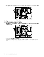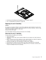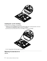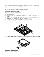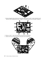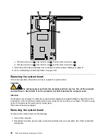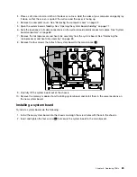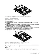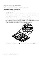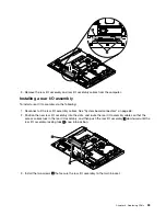
a. Partially remove screw
1
, fully remove screw
3
, and then fully remove screw
1
.
b. Partially remove screw
2
, fully remove screw
4
, and then fully remove screw
2
.
8. Carefully lift the heat sink assembly off the system board. Place the heat sink assembly on its side on
a clean, flat surface.
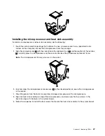
9. Release the microprocessor retention latch
1
by pressing down on the end, moving it to the side,
and releasing it to the open position.
10. Open the microprocessor bracket frame
2
by lifting up the tab on the top edge. Keep the bracket
frame in the open position.
11. Carefully lift the microprocessor
1
straight up and out of the socket, and place it on a static-protective
surface.
86
ThinkCentre Hardware Maintenance Manual
Summary of Contents for ThinkCentre A70z ALL-IN-ONE
Page 1: ...ThinkCentre Hardware Maintenance Manual Machine Types 0401 0421 0994 1165 1184 1186 and 2565 ...
Page 2: ......
Page 3: ...ThinkCentre Hardware Maintenance Manual Machine Types 0401 0421 0994 1165 1184 1186 and 2565 ...
Page 15: ...Chapter 2 Safety information 9 ...
Page 19: ...Chapter 2 Safety information 13 ...
Page 20: ...1 2 14 ThinkCentre Hardware Maintenance Manual ...
Page 21: ...Chapter 2 Safety information 15 ...
Page 27: ...Chapter 2 Safety information 21 ...
Page 31: ...Chapter 2 Safety information 25 ...
Page 46: ...40 ThinkCentre Hardware Maintenance Manual ...
Page 188: ...182 ThinkCentre Hardware Maintenance Manual ...
Page 192: ...186 ThinkCentre Hardware Maintenance Manual ...
Page 193: ......
Page 194: ...Part Number 71Y7087 Printed in USA 1P P N 71Y7087 71Y7087 ...

