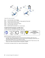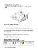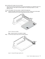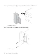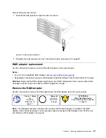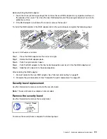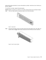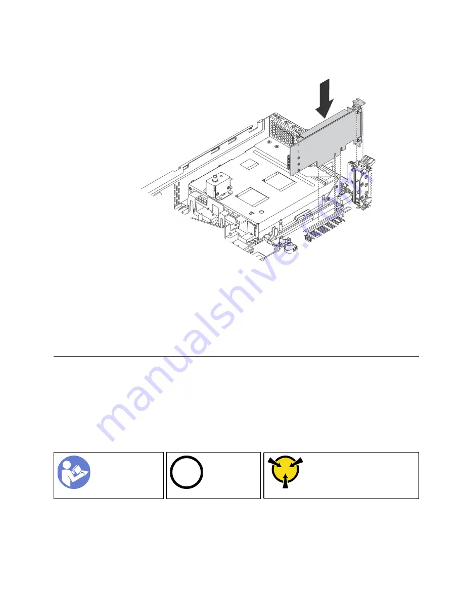
Step 1. Position the PCIe adapter near the PCIe slot. Then, carefully press the PCIe adapter straight into
the slot until it is securely seated and its bracket also is secured by the chassis.
Figure 42. Installing a PCIe adapter on the system board
Step 2. Pivot the PCIe adapter retention latch to the closed position to secure the PCIe adapter in position.
After installing the PCIe adapter on the system board:
1. Refer to your record to reconnect the cables.
2. Complete the parts replacement. See “Complete the parts replacement” on page 32.
Rack latches replacement
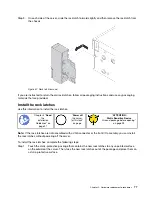
Use this information to remove and install the rack latches.
Note:
Depending on the model, the left rack latch might be assembled with a VGA connector and the right
rack latch might be assembled with the front I/O assembly.
Remove the rack latches
Use this information to remove the rack latches.
“
Power off
the server
for this task”
on page
Ground package before opening”
Note:
If the rack latches are not assembled with a VGA connector or the front I/O assembly, you can remove
the rack latches without powering off the server.
Before removing the rack latches:
.
Hardware replacement procedures
73
Summary of Contents for ThinkAgile MX Certified Node 2U
Page 1: ...User Guide for ThinkAgile MX Certified Node 2U Machine Type 7Z20 ...
Page 4: ...ii User Guide forThinkAgile MX Certified Node 2U ...
Page 14: ...10 User Guide forThinkAgile MX Certified Node 2U ...
Page 38: ...34 User Guide forThinkAgile MX Certified Node 2U ...
Page 94: ...90 User Guide forThinkAgile MX Certified Node 2U ...
Page 98: ...94 User Guide forThinkAgile MX Certified Node 2U ...
Page 100: ...96 User Guide forThinkAgile MX Certified Node 2U ...
Page 103: ......
Page 104: ......

