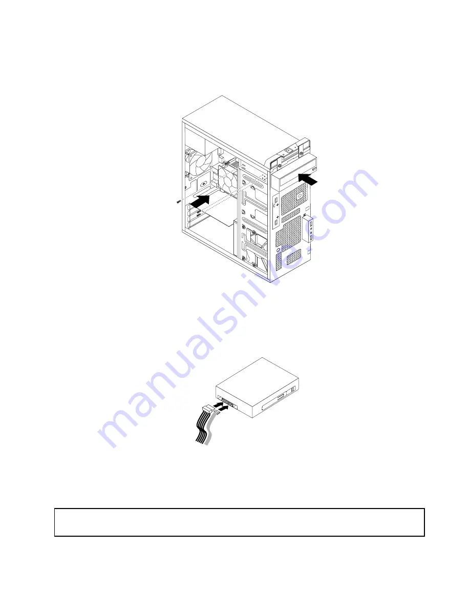
5. Slide the new optical drive into the drive bay from the front and align the screw holes in the new optical
drive with the corresponding holes in the drive bay. Then, install the three screws to secure the new
optical drive in place.
Figure 17. Installing the optical drive
6. Connect one end of the signal cable to the rear of the new optical drive and the other end to an available
SATA connector on the system board. See “Locating parts on the system board” on page 65. Then,
locate an available five-wire power connector and connect it to the rear of the new optical drive.
Figure 18. Connecting the optical drive
7. To complete the installation or replacement, go to “Completing the parts replacement” on page 102.
Replacing the heat sink and fan assembly
Attention:
Do not open your computer or attempt any repair before reading and understanding Chapter 1 “Safety information”
on page 1.
This section provides instructions on how to replace the heat sink and fan assembly.
Chapter 8
.
Replacing FRUs
79
Summary of Contents for 10155
Page 1: ...Lenovo M5800 Hardware Maintenance Manual Machine Types 90AH and 10155 ...
Page 6: ......
Page 13: ...Chapter 1 Safety information 7 ...
Page 17: ...Chapter 1 Safety information 11 ...
Page 18: ...1 2 12 Lenovo M5800 Hardware Maintenance Manual ...
Page 19: ...1 2 Chapter 1 Safety information 13 ...
Page 24: ...1 2 18 Lenovo M5800 Hardware Maintenance Manual ...
Page 25: ...1 2 Chapter 1 Safety information 19 ...
Page 28: ...22 Lenovo M5800 Hardware Maintenance Manual ...
Page 32: ...26 Lenovo M5800 Hardware Maintenance Manual ...
Page 54: ...48 Lenovo M5800 Hardware Maintenance Manual ...
Page 60: ...54 Lenovo M5800 Hardware Maintenance Manual ...
Page 74: ...68 Lenovo M5800 Hardware Maintenance Manual ...
Page 110: ...104 Lenovo M5800 Hardware Maintenance Manual ...
Page 119: ......
Page 120: ......


