background image

14

INSTALACIÓN DEL TERMOSTATO  /  

THERMOSTAT INSTALLATION

  /  

HET INSTALLEREN VAN DE THERMOSTAAT  /  

THERMOSTATEINBAU

  /

 INSTALLATION DU THERMOSTAT  /  

INSTALAÇÃO DO TERMOSTATO

1

2

3

4

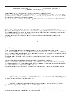
* Inserte un destornillador de punta plana o una moneda 1/8” en la ranura situada en el centro de la 

parte inferior de la caja del termostato y gírelo ¼ vuelta. Cuando note u oiga un “clic”, coja la caja por los
dos extremos inferiores y sepárela de la base inferior, tal como se muestra en el diagrama de la derecha.

En algunos modelos es necesario hacer más fuerza que en otros al separar la caja de la base inferior 
debido al número de terminales que hay en esta última.  /

* Insert a flat blade screwdriver or a coin 1/8” into the slot located in the bottom center of the thermostat 

case and twist ¼ turn.  When you feel or hear a “click”, grasp the case from the bottom two corners and 
separate form the subbase as shown in the diagram at the right.

Some models require more force than others when separating due to the number of terminals on the 
subbase.


 /


* Een schroevedraaier met platte kop of een muntstukje in de groef steken die zich in het midden 

onderaan de omkasting van de thermostaat bevindt en deze een kwartslag draaien. Wanneer u een "klik" 
voelt of hoort, de omkasting onderaan bij de beide hoeken vastpakken en van de thermostaat lostrekken 
zoals in de rechter tekening getoond wordt.

Bij enkele van de modellen dient iets meer kracht gebruik te worden om de omkasting van de 
bodemplaat los te trekken als gevolg van een groter aantal klemmen op de grondplaat.


/


* Stecken Sie einen flachen Schraubenzieher oder eine 1/8" Münze in den Schlitz in der unteren Mitte 

des Thermostatgehäuses und drehen Sie eine ¼ Umdrehung. Wenn Sie glauben ein "Klick" gehört zu haben,
nehmen Sie das Gehäuse an den unteren beiden Ecken auf und trennen es von der Grundplatte, wie es 
auf dem rechten Diagramm gezeigt wird.

Einige Modelle benötigen mehr Kraft als andere beim Auseinandernehmen, je nach Anzahl der 
Klemmen auf der Grundplatte.


/

     * Introduisez un tournevis à pointe plate ou une pièce de monnaie de 1/8" dans la rainure située au centre 
de la partie inférieure de la boîte du thermostat et faites-la tourner d'un 1/4 de tour. Lorsque vous sentirez 
ou entendrez un "clic", prenez la boîte par les deux coins inférieurs et écartez-la de la base inférieure, comme 
on le montre sur le diagramme de droite.

Sur certains modèles, il faut exercer une plus grande pression que sur d'autres, au moment de 
séparer la boîte de la base inférieure, du fait du nombre de bornes se trouvant dans cette dernière.  
     

* Introduza um desaparafusador de ponta plana ou uma moeda 1/8" na ranhura situada no centro da 

parte inferior da caixa do termostato e gire-o 1/4 volta. Quando note ou ouça um "clic" puche a caixa pelos 
dois extremos inferiores e sepáre-a da base inferior, tal como se mostra na figura da direita.

Em alguns modelos é necessário fazer mais força que noutros ao separar a caixa da base inferior 
devido ao número de terminais existente nesta última.

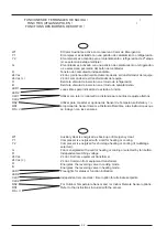
     * Separe el termostato de la parte inferior.  /

    * Swing the thermostat out from the bottom.

  /

     * De thermostaat van het ondergedeelte losnemen.  /

     * Schwenken Sie das Thermostat unten weg. 

 /

     * Séparez le thermostat de la partie inférieure.  /
     * Separe o termostato da parte inferior.

     * Levante el termostato y apártelo de la base inferior.  /

     * Lift the thermostat up and off the subbase.

  /

     * De thermostaat bij de onderkant openklappen en uit de bodemplaat nemen.  /

     * Heben Sie das Thermostat von der Grundplatte ab.

  /

     * Soulevez le thermostat et écartez-le de la base inférieure. /
     * Levante o termostato e sepáre-o da base inferior.

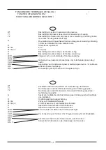
     * Coloque la apertura rectangular que hay en la base inferior sobre los cables de control del equipo que 
salen de la pared y, utilizando la base como una plantilla, marque la posición de los dos agujeros de montaje 
(el montaje totalmente vertical sólo es necesario por razones estéticas).  /

     * Place the rectangular opening in the subbase over the equipment control wires protruding form the wall 
and, using the subbase as a template, mark the location of the two mounting holes (exact vertical mounting 
is necessary only for appearance).

  /

Summary of Contents for 123B-600

Page 1: ...PE 2 KOMPRESSOREN MIT ZUS TZLICHER W RME POMPE CHALEUR 2 COMPRESSEURS AVEC CHALEUR AUXILIAIRE BOMBA DE CALOR 2 COMPRESSORES COM CALOR AUXILIAR 123B 600 INSTRUCCIONES DE FUNCIONAMIENTO E INSTALACI N OP...

Page 2: ...LEREN HET INSTALLEREN VAN DE THERMOSTAAT KEUZE SCHAKELAAR STANDEN SPECIFICATIES FUNCTIES UITGANGSPOLEN OPMERKING 1 2 13 3 4 10 11 11 12 13 24 14 17 17 18 19 21 22 24 25 26 INHALTSVERZEICHNIS BEDIENUNG...

Page 3: ...s Wij verzoeken u deze aanwijzingen door te lezen zodat u met de verschillende functies ervan vertrouwd kan raken en u optimaal profijt zult hebben van dit unieke elektronische besturingssysteem Unser...

Page 4: ...het display aan te geven Ook biedt de thermostaat de mogelijkheid om te kiezen tussen een constant gebruik van de ventilator hetgeen nuttig is bij gebruik van een luchtfilter of het inschakelen van de...

Page 5: ...no indicador Controla tanto el sistema de calefacci n como el de refrigeraci n cambio autom tico durante 5 segundos aparece la palabra AUTO en el indicador Controls both heating and cooling systems a...

Page 6: ...ra o pulsando sem solt los os bot es e O ponto de ajuste de temperatura aparece reflectido durante 5 segundos no indicador CALEFACCI N HEATING VERWARMING HEIZUNG CHAUFFAGE AQUECIMENTO Seleccione la te...

Page 7: ...auf den FAN Knopf dr cken und auf der Anzeige erscheint Das wird f r elektronische Luftreinigung oder bei st ndigem Ventilationsbedarf empfohlen Le ventilateur se met automatiquement en marche lorsque...

Page 8: ...terior Se a op o n o est ligada no termostato aparecer ANULACI N LIMITADA LIMITED OVERRIDE BEPERKTE ANNULERING BESCHR NKTE AUSSERKRAFTSETZUNG ANNULATION LIMIT E ANULA O LIMITADA Cuando el teclado est...

Page 9: ...ostaat zojuist ge nstalleerd dan geeft het display het symbool aan voor de dagtemperatuur Door op de toets DAY NIGHT DAG NACHT te drukken of op de klemmen CLK1 en CLK2 aan de achterzijde van de thermo...

Page 10: ...ne horloge chronom tre t l command e DSP AT ou quivalent le thermostat peut passer alternativement des points de r glage de jour ceux de nuit de fa on automatique Seu termostato LENNOX est equipado co...

Page 11: ...tici n de calor Aux Cuando el interruptor se ponga en la posici n normal el termostato permitir que el compresor y el calor Aux funcionen al mismo tiempo Your LENNOX thermostat is equipped to enhance...

Page 12: ...nktionieren als ob der Strom nie ausgefallen w re Votre thermostat utilise les derniers progr s en mati re de technologie lectronique l tat solide L une des caract ristiques uniques de votre thermosta...

Page 13: ...in l mite los da os derivados de defectos p rdida de uso o mal uso This warranty does not apply in the event of misuse abuse or as a result of unauthorized alterations or repairs The manufacturer will...

Page 14: ...ans une zone du b timent fr quemment occup e De surcro t il doit tre situ 18 46 cm au moins de tout mur ext rieur et 5 environ 1 5 m au dessus du sol dans un endroit o l air circule librement une temp...

Page 15: ...ahl der Klemmen auf der Grundplatte Introduisez un tournevis pointe plate ou une pi ce de monnaie de 1 8 dans la rainure situ e au centre de la partie inf rieure de la bo te du thermostat et faites la...

Page 16: ...eleverde schroeven bevestigen Niet te strak aandraaien Verwenden Sie die mitgelieferten Verankerungen und Schrauben zur Installation auf der trockenen Wand oder dem Gips bohren Sie 2 3 16 5 mm L cher...

Page 17: ...erior izquierdo de la parte posterior del termostato Before the thermostat is re installed on the subbase install the optional clock timer indoor remote sensor and outdoor remote sensor if used Refer...

Page 18: ...t the top of the subbase De thermostaat in the scharnierlipjes aan de bovenkant van de bodemplaat bevestigen Halten Sie das Thermostat auf die Scharniere die sich auf dem oberen Teil der Grundplatte b...

Page 19: ...EYBOARD LOCKED TOETSENBORD VERGRENDELD TASTATUR BLOCKIERT CLAVIER BLOQU TECLADO BLOQUEADO 8 AHORRO ECONOMY ZUINIG GEBRUIK SPARMODUS ECONOMIES ECONOMIA 9 CONFORT COMFORT COMFORT KOMFORT CONFORT CONFORT...

Page 20: ...ooling 60 to 108 F in 1 Steps 16 to 40 C in 1 Steps 28 to 124 F or 0 to 48 C 50 to 124 F or 48 to 48 C 5 C at 20 C 1 F at 68 F between heating and cooling 2 F or 1 C Rated Voltage Rated A C Current Ra...

Page 21: ...n de 60 108 F intervalles de 1 de16 40 C intervalles de 1 De 28 124 F ou de 0 48 C De 50 124 F ou de 48 48 C 5 C 20 C 1 F 68 F entre chauffage et r frig ration 2 F ou 1 C Tension nominale Courant alte...

Page 22: ...te continua debe estar conectado al terminal de 24 V c This thermostat may be used with 24 Volt DC The negative side of the DC supply must be wired to the 24 V terminal Op deze thermostaat kan ook 24V...

Page 23: ...on reloj cron metro a distancia para puntos de ajuste alternos Utilizar para conectar el opcional de Sensor de Temperatura Exterior y o el opcional de Sensor Interior a Distancia Remitirse a las instr...

Page 24: ...oor de optionele opnemer buitentemperatuur en of optionele afstand opnemer raadpleeg De aanwijzing die bij de sensoren meegeleverd zijn W1 Y1 Y2 G R 24 Vac 24 Vac c O B LED1 LED2 CLK1 CLK2 RS2 RS1 RS...

Page 25: ...lisez pour connecter l option de Capteur de Temp rature Ext rieure et ou l option de Capteur Int rieur t l command Fait r f rence aux instructions jointes aux capteurs W1 Y1 Y2 G R 24 Vac 24 Vac c O B...

Page 26: ...25...

Page 27: ...26...

Page 28: ...derungen vorbehalten Sous r serve de toutes modifications ventuelles Equipamentos est o sujeitos a altera es sem aviso pr vio SOCIEDAD DEL GRUPO HCF LENNOX MEMBER OF HCF LENNOX GROUP REFAC B V MAAKT D...

Reviews: