


34
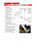
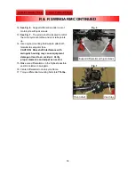
18. Ensure adequate clearance between drive
shaft and swingarm tunnel.
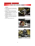
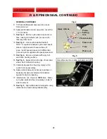
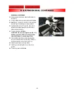
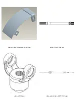
19.
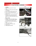
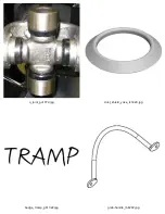
See Fig. 8
. Install (2) u-bolts, (4) lock washers
and (4) nuts to install yoke to pinion shaft.
20. Tighten bolts using 1/2” wrench. Be sure to
tighten both sides equally from both side to
side and top to bottom.
21. Torque u-bolts to
20 ft-lbs.
CAUTION: Do not over-tighten u-bolts. The
bearing cups may distort, causing prema-
ture joint failure or u-bolts may break.
22. Reconnect braided brake line to brass “T.”
Torque banjo bolt to
16 ft.-lbs
.
23. Fill brake fluid reservoir with DOT 4 brake fluid.
24. Secure left side braided brake line and park
brake cable to left side of swingarm using (3)
black zip-ties.
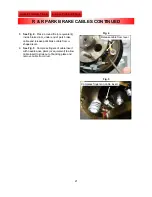
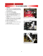
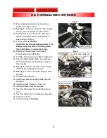
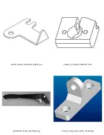
25.
See Fig. 9
. Secure vent tube and park brake
cables using (3) high-temp zip-ties.
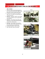
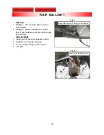
26.
See Fig. 10
. Secure vent tube using (2) black
zip ties.
27. Re-attach electrical box.
28. Install new cable ties to attach brake lines to
swingarm.
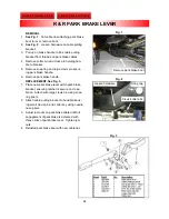
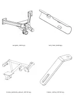
29. Install park brake bracket to frame rail.
30. Install park brake bracket hardware.
31. See “R & R Exhaust” for reinstallation proce-
dure.
32. See “R & R Body” for re-installation procedure.
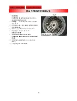
33. Install rear wheels.
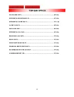
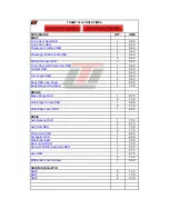
34. Torque lug nuts to
75 ft.-lbs.
Fig. 8
Install u-bolts
Fig. 9
High-temp. cable ties
Fig. 10
Black cable ties
R & R SWINGARM CONTINUED