background image

CONFIGURING YOUR DISPLAY HEIGHT (OPTIONAL, CONTINUED)

3

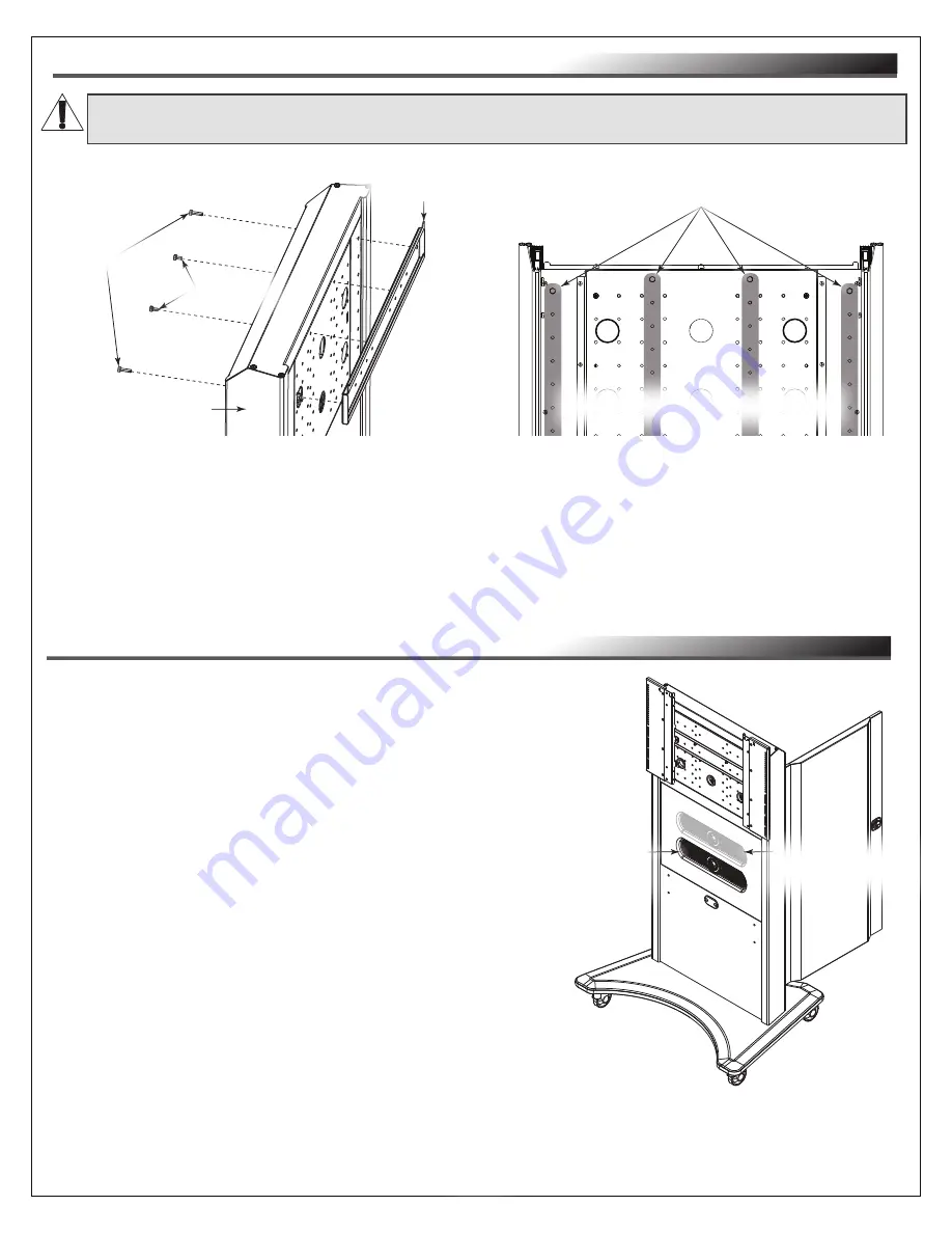
. Determine the proper height for reattaching the horizontal mounting bracket by referring 

to the  


  information provided with your display for an accurate height measurement and considering the    

  clearance provided when your camera is in the default and changed positions.

4. Use removed screws from the previous steps and the available mounting points on your cart to  


  reattach the bracket to the new location

.

FIGURE D

WARNING: 

Never configure the height with your display attached.

AVERTISSEMENT:

 Ne configurez jamais la hauteur avec votre écran attaché.

(2x) ¼-20 x ½”

Inner Bolts

(2x) ¼-20 x 1”

Outer Bolts

Cart

Horizontal 

Mounting Bracket

Available mounting points for the Horizontal Mounting Bracket.

NOTE

: Columns shaded for clarity.

View of the cart with the rear door removed.

Page 9

NOTE

: Use the following steps to change the height of 

your Flush-Mount Camera (FC) from its factory default 

36” (914 mm) height to a 42” (1066 mm) height, if 

desired. (

FIGURE E

)

1. Open the rear door on your FlexView Conferencing  

    Cart as shown.

2. Temporarily remove any devices, cables, and cable  

    management from the inside of your cart.

3. Remove 10” Lever Lock™ plate (B) and 

    2” channels (C) from inside your cart.

For more information, see "Removing Lever Lock Plate 

and Channels" on page 15.

CHANGING YOUR FLUSH-MOUNT CAMERA (FC) HEIGHT (OPTIONAL)

FIGURE E

Rear 

Door

At 36” (914 mm)

Camera Height

(Factory Default)

At 42” (1066 mm) 

Camera Height

(Shaded, Changed Location)

Summary of Contents for MIDDLE ATLANTIC FlexView Series

Page 1: ...T FC FVS HSFC 800SC WH Instruction Sheet Thank you for purchasing a FlexView Conferencing Cart with HuddleSHOT FC Flush Mounted Camera Please read these instructions thoroughly before installing or as...

Page 2: ...ional 8 9 Changing Your Flush Mount Camera FC Height Optional 9 11 Selecting Correct Interface Bracket Hardware for Your Display 12 Installing the VESA 800 Display Adapter Brackets Optional 12 Attachi...

Page 3: ...the bottom of the bays not near the top in order to help prevent the possibility of the furnishing tipping over CAUTION The appliance is not intended for use by young children or infirm persons withou...

Page 4: ...de graves blessures des dommages l quipement ou invalider la garantie Il est la responsabilit de l installateur utilisateur de s assurer que ce produit est charg conform ment aux sp cifications Consig...

Page 5: ...t at av support legrand com or 866 977 3901 2x 2 Lever Lock Channel NOTE Pre Installed Inside FlexView Conferencing Cart C 4x Leveling Foot and Plate A 10 Lever Lock Plate NOTE Pre Installed Inside Fl...

Page 6: ...ng The FlexView Conferencing Cart with HuddleSHOT FC FVS HSFC 800SC WH Instruction Sheet 100 00057 The FlexView Conferencing Cart Front Shelf Option FVS HS FRTSHLF WH Instruction Sheet 100 00058 The F...

Page 7: ...Page 7 CONSIDERING DISPLAY AND CAMERA HEIGHTS NOTE Your display not provided attaches to a pre installed horizontal mounting bracket on your FlexView conferencing cart FIGURE A With casters your pre...

Page 8: ...replace them with the provided leveling feet if desired 1 With at least one additional person carefully tip your FlexView Conferencing Cart over and gently place it onto an appropriate section of flo...

Page 9: ...1 Outer Bolts Cart Horizontal Mounting Bracket Available mounting points for the Horizontal Mounting Bracket NOTE Columns shaded for clarity View of the cart with the rear door removed Page 9 NOTE Use...

Page 10: ...10 32 x screws from the camera panel with the HuddleSHOT FC still attached FIGURE G FIGURE G NOTE The 6x 10 32 x screws are shown in black for clarity Back of Camera Panel Back of HuddleSHOT FC CAUTIO...

Page 11: ...anel NOTE The 4x 10 32 x screws are shown in black for clarity FIGURE H NOTE With the camera reattached carefully position the panel as shown and verify the microphones on your camera are in the follo...

Page 12: ...h Threaded Insert Thread Depth Indicator Toothpick or Straw Thread Depth Indicator Toothpick or Straw Depth Plus Allowance Mark INSTALLING THE VESA 800 DISPLAY ADAPTER BRACKETS OPTIONAL NOTE Only inst...

Page 13: ...tting and only increase as necessary 5 Use a power driver 2 Phillips bit 4x spacers I N if required 4x washers I P and 4x correct length pan head screws I A I M to attach the brackets F to the back of...

Page 14: ...eur de chaque support d interface n est pas fermement install sur le rail sup rieur du support de montage horizontal WARNING This procedure requires at least one additional person AVERTISSEMENT Cette...

Page 15: ...adapter bracket NOTE The door on your cart comes pre assembled the hinges inserted into holes on the left side and the catch is located on the right This topic may be used to reverse the door if desir...

Page 16: ...te or channel must be inserted into adapter brackets at the same depth in order to function correctly Use 20x 6 washers K for equipment mounting convenience UNDERSTANDING CABLE MANAGEMENT Channel Insi...

Reviews: