Page 8
INSTALLING THE LEVELING FEET (OPTIONAL)
CONFIGURING YOUR DISPLAY HEIGHT (OPTIONAL)
NOTE
:
•
Only configure your display height and move your horizontal mounting bracket (X) from its 61”
(1549 mm) pre-installed height after considering your display requirements and camera height
preferece. For more information, see “Considering Display and Camera Heights” on page 7.
•
Adjust torque on power driver to lightest setting and only increase as necessary.
1. Use power driver and 7/16
”
socket to remove (2x) ¼-20 x 1” outer hex bolts from the back of your
FlexView conferencing cart as shown.
(
FIGURE D
)
2. Use driver
and 7/16
”
socket to r
emove
(2x) ¼-20 x ½” inner hex bolts from, the back of your cart and
release the horizontal mounting bracket.
3. Repeat the process to remove all 4 casters from your cart.
NOTE
: Adjust torque on power driver to lightest setting and only increase as necessary.
NOTE
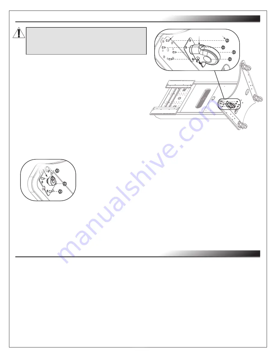
: You can remove the (4x) pre-installed casters
on the bottom of your FlexView Conferencing Cart and
replace them with the provided leveling feet, if desired.
1. With at least one additional person, carefully tip your
FlexView Conferencing Cart over and gently place it onto
an appropriate section of floor to act as a work surface.
2. Use a power driver, ½” socket, and remove
(4x) 5/16-18 flange nuts from the studs on the base
of your cart. Remove caster and set aside the nuts
for leveling feet installation. (
FIGURE B
)
FIGURE B
Caster
Studs
Nuts
WARNING:
This procedure requires at least one
additional person.
AVERTISSEMENT:
Cette procédure nécessite
au moins une personne supplémentaire.
4. Use power driver, socket, and (4x) nuts from the previous steps to
install a leveling foot (A) to the bottom of your cart. (
FIGURE C
)
5. Repeat the process to install all 4 leveling feet to your cart.
6. Make initial adjustments to the leveling feet by tightening (retracting) or
loosening (extending) them as necessary.
7. With at least one other person bracing the bottom end of the cart, carefully lift the top end and gently
place it upright onto the leveling feet.
8. Have someone slightly tip the cart while another person carefully makes any necessary final leveling
feet adjustments.
FIGURE C
A


