background image

Legend Gas Fires recommend that this appliance is serviced at regular 12 monthly intervals. The
chimney or flue should also be checked regularly to ensure that all products of combustion are entering
the flue and there is no excessive build up of soot.
It is the users responsibility to ensure that the appliance is kept in a clean serviceable condition.

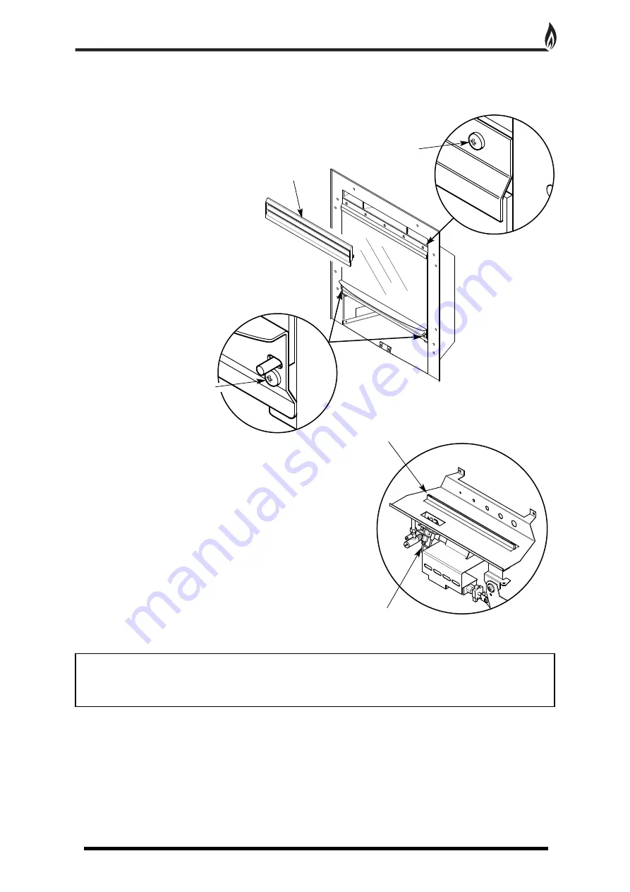
To remove the glass

1. Remove the magnetic trim.

2. Remove the louvred panel by lifting 
up and pulling forwards.

3. Slacken the five machine screws on 
the top retaining strip (Fig. 9).

4. Unscrew the two securing screws 
from the lower infill panel and remove the panel. 
Tilt the glass forwards and slide out (Fig. 10).

5. Clean the glass with a damp cloth. For stubborn stains use 
a proprietary cream cleaner or ceramic hob cleaner.

Ceramic Components and Fuel Bed

Debris from any source should be removed with a soft brush. 
Please ensure that any debris including soot deposits are 
removed from the appliance and not left on the fuel bed. 
It is recommended that the user should, on a regular quarterly 
basis, carefully remove all ceramic components and thoroughly 
clean the stainless steel burner strip and the pilot assembly. 
Any build up of debris in this area could affect the 
operation of the appliance (Fig. 11).

NOTE

: It is common to find surface cracks in the ceramic components. This is due to the expansion and

contraction of the ceramic fibres caused by the intense heat that the burner generates. The cracks will not
affect the safe operation of this appliance. However great care must be taken when handling the ceramic
components as they will break if handled incorrectly. Do not use a vacuum cleaner to clean the ceramics.

Radiant Box Ceramic Liners

- Use only a soft brush to remove any soot deposits from the ceramic liners 

during cleaning as this is the only method that can be used to remove deposits. The ceramic liners are very 
delicate and should be treated accordingly.

6. Reassemble in reverse order. The screws should be tightened enough to ensure the glass is sealed. The
glass should be positioned centrally to ensure the decorative trim will fit over it.

Trims and Frets

- The trim and fret should be removed from the appliance for cleaning, please ensure that the

appliance has cooled thoroughly. Metal trims and frets maybe lacquer coated and therefore do not require
polishing.

CLEANING AND MAINTENANCE

10

Stainless Steel Burner Strip

Pilot Assembly

2 x Securing Screws

Fig. 9

Fig. 10

Fig. 11

5 x Machine Screws

Louvred Panel

Summary of Contents for Evora

Page 1: ...llation and then should be handed to the end user when the installation is complete This is an official requirement and is the responsibility of the fitter of this appliance Having installed the appliance the installer should take the necessary steps to ensure that the user fully understands how to operate the appliance and is also made aware of the fire s basic cleaning and maintenance requiremen...

Page 2: ...ure 5 Commissioning 7 Technical Data 7 Replacement Parts 7 Trouble Shooting GAS SAFE Engineer Only 8 User Instructions 9 Cleaning and Maintenance 10 Fire Front Specifications 11 Modular Coal Layout Instructions 12 Modular Pebble Layout Instructions 14 Guarantee 16 Trouble Shooting User 16 CONTENTS 2 ...

Page 3: ...peration The installer must then establish that all the products of combustion are entering the flue within ten minutes of lighting from cold This can be verified by inserting a lit smoke match into the left and right hand ducts immediately above the glass retaing strip It should NOT be inserted into the central convector duct This operation should be carried out before fitting the trim and louvre...

Page 4: ...eness of the flue and to ensure that there is no leakage into another part of the premises including any loft or as appropriate other adjoining premises this is particularly important where a number of chimneys combine into a multiple stack The flue flow test should be carried out using a suitable smoke pellet which the pellet manufacturer claims to generate 5m3 of smoke in 30 seconds burn time Th...

Page 5: ...e radiant box When the box is placed against a flat surface the foam strip will form a seal around the boxes flange 7 Carefully lift the appliance into position in the fireplace opening and check that the flange of the radiant box fits flush against the sealing face with no gaps present 8 Remove the five screws that secure the burner tray to the box two on the front leg two at the rear of the tray...

Page 6: ... optional cable fixing kit provided Drill four holes in the rear of the fireplace opening Fig 5 Securely fix the four eye bolts provided using suitable rawl plugs Feed one cable through each of the top holes in the rear of the fire box 115mm max 500mm min 550mm max 112mm 112mm Tension Nut Cable Clamping Screw Fig 5 Fig 6 Cable Rectangular Cutout Insert cable into rectangular cutout and feed the en...

Page 7: ...der Ref LEG59 5 Glass Rope Seal The integrity of the glass rope seal should be checked on service and replaced if necessary by a Gas Safe Registered Engineer Order Ref LEG58 COMMISSIONING 7 Gas Type Natural Gas G20 Cat I2H Gas Connection 8mm Number of Injectors One Injector size Stereomatic 1 70mm Control Max Operating Temperature 80oc Inlet Pressure Cold 20 mbar Heat Input Gross 4 6 kW Full 3 0 k...

Page 8: ...he coal set as per Ceramic Component Layout Instructions pages 12 15 5 The fire makes a roaring noise when lit Check That the front coal is seated correctly and the pilot hole is positioned correctly over the pilot assembly IF ANY PART OF THE PILOT ASSEMBLY IS SUSPECTED AS BEING FAULTY THE COMPONENT MUST BE REPLACED 6 The flames appear blue after the fire has fully warmed up The coals ceramic line...

Page 9: ...o the top position NOTE The pilot assembly fitted to this appliance has an oxygen depletion sensor built in to monitor the room for products of combustion If the sensor should operate and switches the appliance off re ignite the appliance following the procedure above Should the appliance repeatedly activate the sensor a specialist should be called to inspect the appliance 7 The fire must always b...

Page 10: ...trip and the pilot assembly Any build up of debris in this area could affect the operation of the appliance Fig 11 NOTE It is common to find surface cracks in the ceramic components This is due to the expansion and contraction of the ceramic fibres caused by the intense heat that the burner generates The cracks will not affect the safe operation of this appliance However great care must be taken w...

Page 11: ...e use of a fireguard confirming to BS 6539 such that the approach to the naked flame is minimised CLEANING AND MAINTENANCE CONTINUED 11 w Y X Minimum area free space 15cm2 Minimum area free space 5cm2 Fig 12 Slide Control Lever The slide control mechanism should be greased annually with high temperature grease Place a small amount of grease at the top and bottom of the lever guide and operate the ...

Page 12: ...that the back edge is pushed up against the front of the burner strip Fig 15 CAUTION The coals are extremely fragile and must be handled accordingly Gloves should be worn and any inhalation of dust should be avoided The coals must be kept away from children at all times Never put additional coals on the fire Never use coals other than those originally supplied or genuine Legend Spare Parts Fig 13 ...

Page 13: ...r to achieve the desired flame picture It may be necessary to remove some or all of the coals to clean them at some time Cleaning must only be done using a soft brush 5 Finally check that all the coal pieces are nested together correctly Fig 18 and a close fit is achieved on the middle joint this will stop gas surge through the gap ...

Page 14: ...t the back edge is pushed up against the front of the burner strip Fig 21 CAUTION The pebbles are extremely fragile and must be handled accordingly Gloves should be worn and any inhalation of dust should be avoided The pebbles must be kept away from children at all times Never put additional pebbles on the fire Never use pebbles other than those originally supplied or genuine Legend Spare Parts Fi...

Page 15: ...r to achieve the desired flame picture It may be necessary to remove some or all of the pebbles to clean them at some time Cleaning must only be done using a soft brush 5 Finally check that all the pebble pieces are nested together correctly Fig 24 and a close fit is achieved on the middle joint this will stop gas surge through the gap ...

Page 16: ...emove all the loose coals and the front coal and thoroughly clean any debris in and around the pilot area If the fire will still not light contact your installer 2 The flames appear blue excessive soot deposits The ceramic components including the coal need relaying pages 12 15 Too much or too little room ventilation Seek professional advice 3 Roaring noise coming from the pilot The front coal is ...

Reviews: