44 | 50
© 2021 LeddarTech Inc.
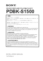
11.3. Transition Time
Fig. 28
: LeddarTech’s current optical setup for transition time (conceptual view)
Table 28: Optical setup legend, transition time
#
Tool
Model Used
A
Optical table
Thorlabs
B
Oscilloscope
LeCroy WaveSurfer 64Xs-A, 2.5 GS/s
C
Mirrors
Thorlabs PF10-03-P01
D
Collimating lens
Thorlabs C230TMD-B
E
Light source
Thorlabs M9-915-0300, 915 nm, 300 mW
F
Screen
Simple black wall
G
Light source control Thorlabs LDM90 + T LDC205C
H
Photodiode
Thorlabs DET10A Si-based detector, 200-1100 nm
I
DBSD
LeddarSteer
J
Vertical polarizer
Thorlabs LPVIS050-MP2
K
DBSD controller
LeddarSteer Evaluation Board
L
Computer
Running Windows 7 or Windows 10 OS
The procedure to evaluate the transition time from one tile to another consists of evaluating, with the help of
the oscilloscope, the time required for the photodetector to output high voltage once the tile ID has been
switched from A to B.