


Hardware
manual of the ES-DH series drives
20
Current Control Detail
Leadshine
’
s easy servo motor is integrated with a high-resolution 1,000-line optical incremental
encoder. That encoder can send the real-time shaft position back to the ES-DH drive. Like traditional
servo controls, the drive can automatically adjust the output current to the motor. The output
current ranges between the holding current and the close-loop current. When there is no pulse sent
to the drive, the ES-DH drive goes into idle mode and the actual motor current is determined by the
holding current percentage (similar to
“
idle current
”
of open loop stepper drives). In normal working
mode, the ES-DH drive monitors the actual shaft position all the time. The current outputted to the
motor changes dynamically based on the tracking error between the actual position and the
commanded position.
Low holding current can reduce motor heating however also reduces the holding torque which is
used to lock the motor shaft at standstill. It is recommended to determine the holding current by
whether or not there is big vibration at start-up and how much lock torque is required, based on your
actual applications.
Fine Tuning
Leadshine already loads default current-loop parameters and position-loop parameters. Those
default parameter values have been optimized. They should be good enough for most industrial
applications, and there is no need to tune them. However, if you want to fine tune the IES for best
performance for your applications, Leadshine also offers tuning software, ProTuner, which allows you
to adjust those current-loop and position-loop parameters (see software manual).
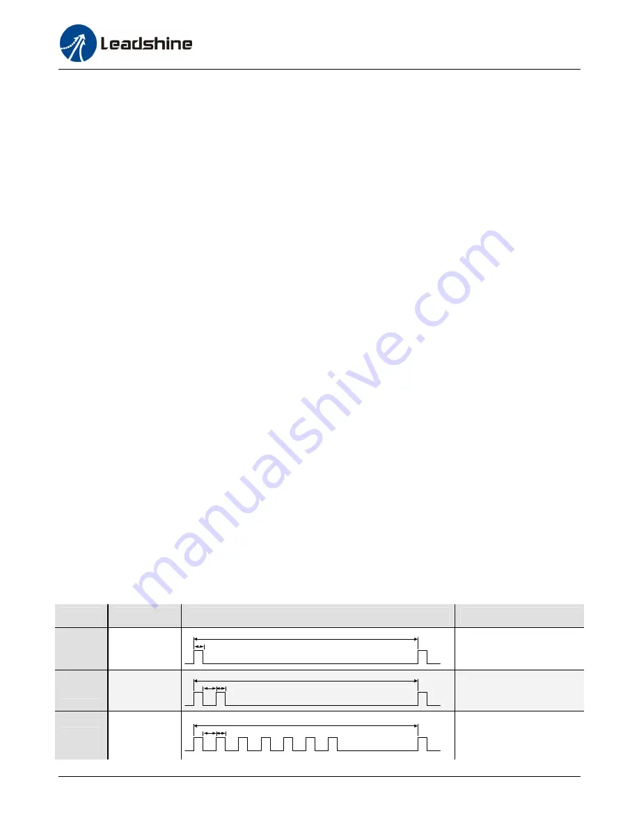
Protection Functions
To improve reliability, the ES incorporates some built-in protection functions. The ES uses one red LED
to indicate the protection type. The periodic time of red is 5 s (seconds), and the blinking times of red
LED indicates what protection has been activated. Because only one protection can be displayed by
red LED, so the drive will decide what error to display according to their priorities. See the following
protection indications table for displaying priorities.
Priority Time(s) of Blink
Sequence wave of RED LED
Description
1st
1
0.2S
5S
Over-current protection
2nd
2
0.2S
0.3S
5S
Over-voltage protection
3rd
7
0.2S
0.3S
5S
Position Following Error


