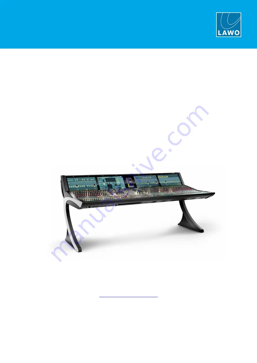
mc²96
Installation & Service Guide
Version: 1.0/3
To obtain the latest documentation and software downloads, please visit:
Edition: 06 February 2021
www.lawo.com/lawo-downloads
Page 1: ...mc 96 Installation Service Guide Version 1 0 3 To obtain the latest documentation and software downloads please visit Edition 06 February 2021 www lawo com lawo downloads...
Page 2: ...ers It cannot be guaranteed that all product names products trademarks requisitions regulations guidelines specifications and norms are free from trade mark rights of third parties All entries in this...
Page 3: ...Server Types 16 3 9 Control Surface Wiring 16 3 10 4 Installation 20 Unpacking 20 4 1 Packing List 20 4 2 Mounting the Frame 21 4 3 Dimensions and Weight 21 4 4 Temperature and Cooling 21 4 5 Minimum...
Page 4: ...placing a User Panel 45 5 6 Replacing a TFT Display 49 5 7 Calibrating a Touch screen 49 5 8 Bayserver Gateserver Switch Settings 50 5 9 Replacing a Console Power Supply 52 5 10 Replacing the Local IO...
Page 5: ...ips useful tips and short cuts Attention alert you when an action should always be observed Further Information Mechanical drawings and data sheets including weights and dimensions are available from...
Page 6: ...all of the instructions provided in the General Safety Information for Lawo Equipment booklet delivered with your devices Double click here to open the same information as a pdf Please also observe t...
Page 7: ...l channel bays may then be added as required Each 16 fader channel bay adds 510mm to the width of the console The position of the central bay is flexible allowing for asymmetrical layouts which differ...
Page 8: ...xy Following transportation split frames must be combined to form a single unit 3 3 Mounting Options mc296 Studio Version with stand Each frame can be ordered for either Studio or OB Van Mobile mounti...
Page 9: ...ders 3 4 1 Single Fader Bays As standard each channel bay is fitted with the following control panels 1 x Channel Display 978 13 A high resolution touch screen TFT display 1 x FC Panel 978 11 with 112...
Page 10: ...y 978 13 Identical to a standard channel bay 1 x Fader Panel Upper 978 12 with 16 x 60mm motorised faders 48 rotary encoders 16 mini TFT displays 214 push buttons Replaces the 978 11 1 x Fader Panel 9...
Page 11: ...bay When fitted to the centre section the display is known as the Central GUI 1 x RTW Panel 978 27 A special version of the RTW TM9 for Lawo consoles 1 x Central Panel Upper 978 21 with 47 rotary enco...
Page 12: ...78 13 Identical to standard centre section 1 x RTW Panel 978 27 Identical to standard centre section 1 x Central Panel Upper 978 21 Identical to standard centre section 1 x Xtra User Panel 978 23 with...
Page 13: ...gurable Unless otherwise specified the console ships with two blanking panels 978 28 User Panel Options Part No User Panel Name Description 978 23 XTRA USER PANEL Must be fitted to an Xtra Main Faders...
Page 14: ...nally to the console s local IO The default configuration sets the AES3 inputs to follow the MON 1 monitor source selector Alternatively signals can be routed directly to the meter using the console G...
Page 15: ...e internal power supplies The heat sink indicates the location of each PSU block within the frame 4 Ethernet Server Back Plates Radiates heat from the internal Ethernet servers The back plates indicat...
Page 16: ...ver Start up Screen for Central Gateserver Rear Connector Panel if Central Bayserver Rear Connector Panel if Central Gateserver 3 10 Control Surface Wiring Internally the control surface uses point to...
Page 17: ...tch ROUTER 1 and ROUTER 2 These must connect directly to the ETHERNET A ports on the Nova73 Router Modules Only one connection is essential for operation If a second Router Module is fitted then a sec...
Page 18: ...Gateserver MGMT A and MGMT B These must connect to the same Management Network as the Core s control ports e g ETHERNET B if the Core is a Nova73 Only one connection is essential for operation A secon...
Page 19: ...ng the mxUpdater utility included with mxGUI After a successful boot the Gateserver connects automatically to its partnered Core by creating a VPN connection between the Gateserver and mc2 control sys...
Page 20: ...ed with the control surface in the Accessories box 2 x 2m IEC power cables country specific to connect mains power to the frame If the surface contains more than one PSU block then additional IEC powe...
Page 21: ...to install then bear this in mind before mounting the frame in its final location 4 4 Dimensions and Weight The dimensions and weight vary depending on the frame variant and control panel options Mech...
Page 22: ...mc 96 Installation Service Guide Version 1 0 3 22 65 4 Installation 4 6 Minimum Distances for Control Surface Mounting Studio Frame OB Van Frame...
Page 23: ...ss operation 1 x USB cable to charge the keyboard To install the keyboard 1 Using the cable provided connect the keyboard to a powered USB port and wait until the keyboard is fully charged 2 Insert th...
Page 24: ...ot required Please note that there is no locking mechanism to anchor the script tray to the console and so it must be removed for transportation When fitted the tray glides to the left or right The ma...
Page 25: ...ER 1 2 or MGMT A B control data to from the Core or Management Network Only one connection is essential for operation the second provides redundancy AES3 MADI GPIO MIC LINE audio and GPIO breakouts fo...
Page 26: ...ements sticker 4 10 3 Mains Connections The MAINS connectors are located on the frame s rear panel There are two connectors one for each of the internal supplies For redundancy it is recommended to co...
Page 27: ...round for EMC reasons 1 Fasten the grounding cable to the rear of the frame using the CASE grounding screw M5 x 12mm The control surface must be on the same potential as all other system devices modul...
Page 28: ...ation Cable CAT 5e straight 1 1 Ethernet cable Connector RJ45 Length up to 80m 4 12 2 Wiring for Gateserver Consoles The MGMT A MGMT B ports must connect to the same Management Network as the Core s c...
Page 29: ...he same manner as the main frame To make the connections use a straight 1 1 network cable of the type CAT 5e with RJ45 connectors The maximum cable length 80m Wiring up to two Extender Frames 1 Connec...
Page 30: ...n additional 4 x AES3 out and 5 x GPO which are wired internally to the RTW meter in the centre section These cannot be accessed externally and so will be unused if the RTW meter is not fitted 4 14 1...
Page 31: ...ysical connections must match the AdminHD configuration Cable Specifications To use the copper ports choose an Ethernet cable that meets the following specification Cable CAT 5 or better CAT 5e 6 7 st...
Page 32: ...iability and easy setup do NOT connect any other network equipment between RAVENNA Link ports RAVENNA Specification When using RAVENNA the interface provides RAVENNA multi channel digital audio over I...
Page 33: ...981 60 10 1000 Base LX 1310nm 3dBm single mode fiber 10km 981 60 20 1000 Base ZX 1550nm 0dBm single mode fiber 80km 981 60 30 1000 Base T RJ45 copper 100m 981 60 60 Installing the SFPs The SFP modules...
Page 34: ...user data 1 x USB marked RTW connects to the RTW TM9 meter Please refer to the TM9 user manual 1 x Stereo Phones HP 1 This stereo phones output can be used to connect a pair of stereo headphones The s...
Page 35: ...n the Central Panel Upper 978 21 can be used to connect a talkback microphone It is wired directly to the male XLR marked TB on the console s rear panel Note that the console does not include a dedica...
Page 36: ...asing shields etc the device MUST be switched off and disconnected from the mains supply Check the unit for electrical safety after completing the work Using the Service Instructions We recommend that...
Page 37: ...e You should perform this procedure if the graphics on an individual display freeze or look odd Or if the controls and indicators on a panel do not respond or update These symptoms can sometimes occur...
Page 38: ...ns supply 1 Remove the screws at the bottom of the panel using a T20 Torx driver The number of screws vary depending on the panel type channel bay panels have three screws while the central panel has...
Page 39: ...er connector The Central Panel Upper has two additional connectors 1 x RJ45 Network and 1 x talkback to the front panel XLR FC Panel Cable Fasteners 5 Carefully remove the panel by lifting it out of t...
Page 40: ...into place It is important that the bolts fit into the holes as shown below and that you press down only above these bolts until the fitting is correct 8 Fasten the screws to secure the panel Once the...
Page 41: ...reaching around the aluminum profile and pushing upwards Then use your fingers to lift the panel away from the frame 4 Remove the cables from their fasteners and unplug the connectors taking note of w...
Page 42: ...you will see the Hood Fastener stowed safely within the frame 2 Release the fastener from its catch and place the ball end into the cut out in the metal plate When you have finished working inside the...
Page 43: ...s being replaced Panel Face up Panel Face down DO NOT attempt to open the frame without first disconnecting the mains supply 1 Remove the Fader Panel from the console frame as described earlier and la...
Page 44: ...ready to fit the replacement 6 Insert the new fader unit into position 7 Carefully lift the panel onto its side supporting the fader from behind and replace the two front panel screws 8 Turn the pane...
Page 45: ...console In our example a new user panel is being fitted to the upper slot Panel Face up Panel Face down DO NOT attempt to open the frame without first disconnecting the mains supply 1 Remove the Centr...
Page 46: ...you push down 4 Turn the complete panel face down to reveal the free slot s If you are working on the upper slot then now is the time to remove the three fixing screws which attach to the thin blankin...
Page 47: ...t is a good idea to fix the four Hex nuts on the side of each user panel first and tighten these to bring the panel flush with the main surface Then fit the remaining Hex nuts and T10 screws For the u...
Page 48: ...ng is secured plug the bridging power connector from each user panel into the main control board as shown below 9 Fit the Central Panel Upper back into the console frame apply mains power and then res...
Page 49: ...attempt to use a short driver or driver attachment damage can occur 2 Remove the connectors taking note of where each one should be fitted Each display has 1 x Display Port 1 x RJ45 1 x USB and 1 x po...
Page 50: ...frame starting at 0 You may need to adjust the settings if you are replacing a TFT display or adding an extender frame Start by setting the S1 DIP Switches 1 2 and 3 to the correct positions as descri...
Page 51: ...s DO NOT attempt to open the frame without first disconnecting the mains supply 1 Remove the TFT display from the bay you wish to adjust as described earlier 2 Locate the S1 DIP switches and SW1 rotar...
Page 52: ...s a pdf To replace a PSU block you will need to remove the TFT display from the PSU bay 1 Turn off the power to the control surface by disconnecting ALL MAINS connectors press the red button on the IE...
Page 53: ...Do NOT disconnect any wires other than those shown 6 Using a 8mm hex socket remove the six nuts holding the PSU block in place Take care NOT to drop any nuts or washers into the desk 7 Remove the PSU...
Page 54: ...mpt to open the frame without first disconnecting the mains supply 1 Disconnect all of the local IO cabling from the console s rear panel See Local IO Connections 2 Remove the upper panels from the ce...
Page 55: ...rame Take care that the frame does not scrape the unit and that the cables do not get caught 6 Slide the replacement unit into the console frame taking care not to scratch the unit or get any cables c...
Page 56: ...To replace the switch you will need to remove the upper panel from the channel bay housing the switch DO NOT attempt to open the frame without first disconnecting the mains supply 1 Remove the upper p...
Page 57: ...onsole frame Take care that the frame does not scrape the unit and that the cables do not get caught 5 Slide the replacement unit into the console frame taking care not to scratch the unit or get any...
Page 58: ...open the frame without first disconnecting the mains supply 1 Remove the Central Panel Upper 978 21 as described earlier and lay it face down on a piece of foam or similar ESD proof protective materia...
Page 59: ...the underside 6 Then fit the power cable to the replacement and position the new computer into place Secure the unit to the control panel using the four Torx 10 screws 7 Reconnect all of the cables to...
Page 60: ...Central Panel Upper 978 21 Xtra Central Panel Lower 978 22 Central User Panel Options Xtra Keys User Panel 978 23 40 Key User Panel 978 24 Reveal Fader User Panel 978 25 Automation User Panel 978 26...
Page 61: ...Appendices 6 2 Wiring Diagrams The following diagrams show the control surface internal wiring in more detail In each case double click on a link to open the diagram as a pdf Central Audio Wiring Bay...
Page 62: ...a high pass filter and 20dB PAD The maximum analog input level with the PAD enabled is 24dBu 6 3 2 Talkback TB 3 pin XLR connector male This connector is wired from the 3 pin female XLR Talkback conne...
Page 63: ...s conform to the stereo AES3 standard 6 3 6 MADI The console s MADI interface conforms to AES 10 and supports up to 64 bi directional channels at 48kHz or 32 channels at 96kHz To use the interface you...
Page 64: ...mc 96 Installation Service Guide Version 1 0 3 64 65 6 Appendices 6 3 7 GPIO 37 pin D type connector DB37 female 6 3 8 Headphones 6 35mm stereo jack connector...
Page 65: ...en from path 2 And vice versa The result is that the receiver can switch from one path to the other without impacting upon the stream content The network class determines how much delay between the tw...