


LAUNCH
Installation Instruction for Economical Symmetric Floor-plate 2-post Lift
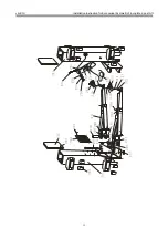
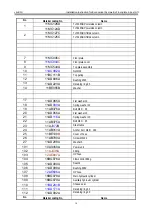
7
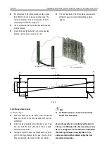
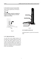
falling of the column.
The wire protective pipe on the floor plate must
be in same direction with the pipe on the column
near the base. And the floor plate would be placed
in front position.
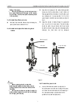
5.2.5 Install the offside column
z
Drill holes and install the offside column following the
same procedures as outlined in 5.2.3
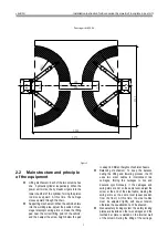
5.2.6 Install and adjust the balancing steel
cables
z
Raise the two carriages to the safety locking position
(make sure that the safety locks on each column are
fully engaged before attempting to install cables), and
two carriages are in equal position from the floor
(same height). Install the two steel cables as shown in
Fig. 6.
z
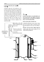
Adjust the tension of cables through the adjustment
nuts on each end of steel cable. The steel cables
should be tight in equal tension. Each steel cable
should be ensured in the pulley when adjusting tightly,
otherwise the steel cable will be damaged.
Figure 6
Note:
Before operating the lift, re-check the
balancing steel cables and ensure they are not
wrongly installed. Ensure the steel cables still in
the pulley.
The two steel cables are required to adjust to
certain uniform tension to ensure the two carriages
are moving synchronously.
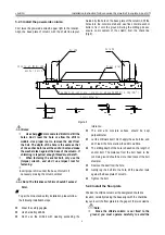
5.2.7 Install the power unit
z
Use two M10 bolts and washers (as Figure 8) to
secure the power unit. After the securing of the power
unit, fill the reservoir with hydraulic oil (oil capacity of
10L). Operate carefully to avoid dust and other
pollutants mixed with the hydraulic oil.
M16 nuts
Adjustment nuts
Long thread end
Steel cable


