78
LAUNCH
X-431 PAD V
User's Manual
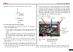
on/off of primary circuit is not opening/closing of mechanical contact,
but the conduction of transistor. The primary voltage has no obvious
oscillations within the duration, but the voltage increases during the
magnetization process due to current limiting, and this change can
cause corresponding fluctuations of secondary voltage line as a result
of induction of ignition coil.
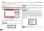
Fig. 7-44
7.4.4 Waveform analysis mode
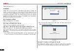
The ignition secondary single-cylinder waveform test is mainly used to:
a. Analyze the ignition dwell angle of single cylinder.(ignition coil
charging time)
b. Analyze the capability of ignition coil and secondary high tension
circuit (from ignition line to ignition voltage line).
c. Find the improper mixture A/F ratio of single cylinder (from
combustion line).
d. Analyze the capability of capacitance (platinum or ignition system).
e. Find the spark plug that causes misfire of the cylinder (from
combustion line).
This test can provide very meaningful information about the
combustion quality for each cylinder. If necessary, this test can also
be performed during driving. Since the secondary ignition waveform
is significantly affected by different engines, fuel systems and ignition
conditions, it is useful for detecting the faults of engine mechanical
parts, fuel system components, and ignition system components.
Different parts of the waveform can specify that some components and
systems on the specific cylinder have faults. Refer to the instructions
for various parts of waveform for the related component working status
of specific waveform section.
Test methods and conditions:
Start the engine or drive the vehicle according to the driving
performance fault or poor ignition, etc. Confirm the consistence
of judgment standard (the amplitude, frequency, shape and pulse
width, etc., for each cylinder), check the fault of the waveform for
corresponding components.
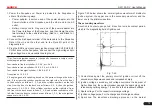
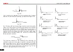
Waveform results: observe the ignition coil at the beginning of
charging, the relative consistent falling edge represents the dwell
angle and ignition timing of each cylinder are precise.
Ignition line:
Observe the height consistence of flashover voltage. Too high
flashover voltage (even out of the oscilloscope screen) represents a
high resistance existed in the ignition secondary circuit (for example,
open circuit, or damaged spark plug or high voltage line, or too
large time gap on spark plug), while the too short sparking voltage
represents the resistance of ignition secondary circuit is lower than
normal value (due to pollutant and broken spark plug or the high
voltage line of spark plug has electrical leakage, etc.).
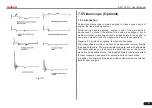
Spark or combustion voltage:
Observe the consistence of spark or combustion voltage, as it
represents the consistence of spark plug and the air-fuel ratio of each


