68
LAUNCH
X-431 PAD V
User's Manual
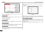
There are two ways available for channel selection:
A. Select from the channel tab shown at the bottom of the waveform
display area
B. Select from Vertical settings
*Note: For better comparison and identification, each channel and
waveform are marked in different colors.
Fig. 7-26
<2> Channel attributes & trigger setting
Channel attributes can be set via horizontal settings and vertical
settings.
Horizontal Settings
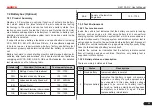
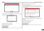
User can make some settings directly by tapping < or > next to
options.
Fig. 7-27
Time/DIV: Horizontal scale. If the waveform acquisition is stopped
(using the / button), the Time/DIV selector expands or compresses
the waveform.
Y-T format: The conventional oscilloscope display format. It shows the
voltage of a waveform record (on the vertical axis) as it varies over
time (on the horizontal axis).
Vertical Settings
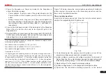
The trigger determines when the Scopebox starts to acquire data and
display a waveform. When a trigger is set up properly, it can convert
unstable displays or blank screens into meaningful waveforms.
When the Scopebox starts to acquire a waveform, it collects enough
data so that it can draw the waveform to the left of the trigger point.
The Scopebox continues to acquire data while waiting for the trigger
condition to occur. After it detects a trigger, the Scopebox continues to
acquire enough data so that it can draw the waveform to the right of
the trigger point.
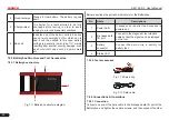
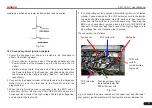
User can make some settings directly by tapping < or > next to
options.
Fig. 7-28
Channel: To select the channel source.
Volts/DIV
: It is defined as “Volts/Division” and mainly used to change
the resolution.

