LAUNCH
X-431 PAD V
User's Manual
69
Coupling: Trigger coupling determines what part of the signal passes
to the trigger circuit. AC, DC and Ground are included:
•
AC: Blocks the DC component of the input signal.
•
DC: Passes both AC and DC components of the input signal.
•
Ground: Disconnects the input signal.
Probe: When using a probe, the Scopebox allows you to select the
attenuation factor for the probe. The attenuation factor changes the
vertical scaling of the Scopebox so that the measurement results
reflect the actual voltage levels at the probe tip.
BW Limit
•
ON: Limits the channel bandwidth to 20MHz to reduce display
noise.
•
OFF: Get full bandwidth.
Invert
•
ON: Invert the selected wave.
•
OFF: Restore to the original display of the waveform.
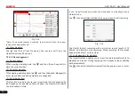
Trigger setting
Trigger indicates that when certain waveform meets the conditions that
are predefined according to the requirements, the Scopebox acquires
the waveform and its adjacent section, and then displays it on the
screen.
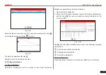
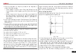
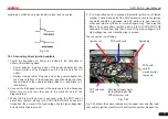
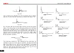
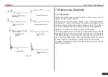
Fig. 7-29
1) If
Edge
trigger is selected (An edge trigger determines whether the
Scopebox finds the trigger point on the rising or the falling edge of
a signal.):
Sweep: The sweep mode determines how the Scopebox behaves in
the absence of a trigger event. The Scopebox provides three trigger
modes: Auto, Normal, and Single.
•
Auto: It allows the Scopebox to acquire waveforms even when it
does not detect a trigger condition. If no trigger condition occurs
while the Scopebox is waiting for a specific period, it will force itself
to trigger.
When forcing invalid triggers, the Scopebox can not synchronize
the waveform, and then waveform seems to roll across the display.
If valid triggers occur, the display becomes stable on the screen.
•
Normal: This mode allows the Scopebox to acquire a waveform
only when it is triggered. If no trigger occurs, the Scopebox keeps
waiting, and the previous waveform, if any, will remain on the
display.
•
Single: In this mode, it only acquires the waveform that generates
for the first time the trigger conditions are met, and then stops after
finishing capture.
Source: Select which channel as trigger signal.
Slope:
•
+ : Trigger on rising edge
•
- : Trigger on falling edge
High Freq Rejection: Reject high frequency signals when selected.
2) If
Pulse Width
trigger is selected (Pulse trigger occurs according to
the width of pulse. The abnormal signals can be detected through
setting up the pulse width condition):

