background image

Copyright © 2017 Lathem Time Corporation. All rights reserved.

Document Number: USG0115 -  Revised: 04/15/2017

Lathem Time

200 Selig Drive SW

Atlanta, GA 30336

www.lathem.com

Tel. (404) 691-1064 

NOTICE:

This equipment has been tested and found to comply with the limits for a Class B 

digital device, pursuant to Part 15 of the FCC Rules. These limits are designed to 

provide reasonable protection against harmful interference in a residential installation. 

This equipment generates, uses, and can radiate radio frequency energy and, if not 

installed and used in accordance with the instructions, may cause harmful interfer-

ence to radio communications. However, there is no guarantee that interference will 

not occur in a particular installation. If this equipment does cause harmful interference 

to radio or television reception, which can be determined by turning the equipment off 

and on, the user is encouraged to try to correct the interference by one or more of the 

following measures:

•  Reorient or relocate the receiving antenna.

•  Increase the separation between the equipment and receiver.

•  Connect the equipment into an outlet on a circuit different from that to which 

  the receiver is connected.

•  Consult the dealer or an experienced radio TV technician for help.

This Class B digital apparatus complies with Canadian ICES-003.

Cet appareil numerique de la classe B est conforme a la norme NMB-003 du Canada.

Lithium battery contains perchlorate material – special handling may apply. 

Visit: http://www.dtsc.ca.gov/hazardouswaste/perchlorate for information about proper methods of disposal.

The information within this document has been carefully checked and is believed 

to be entirely reliable. However, no responsibility is assumed for inaccuracies. 

Lathem reserves the right to make changes to any products herein to improve 

reliability, function, or design.

Summary of Contents for 700E

Page 1: ......

Page 2: ...can be determined by turning the equipment off and on the user is encouraged to try to correct the interference by one or more of the following measures Reorient or relocate the receiving antenna Inc...

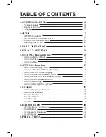
Page 3: ...FAULT SETTINGS 7 2 SETUP 5 SETTING Date and Time Setting the Display Hours Setting the Time Setting the Date 6 SETTING Function Setting the Mode Pay Period Setting the Pay Period Starting Date Days Se...

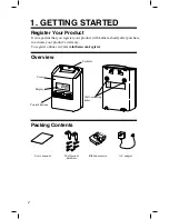
Page 4: ...l Wall mount hardware Ribbon cassette Cover Display Control buttons Card slot Wall mounting holes AC adapter It is important that you register your product with Lathem shortly after purchase to activa...

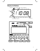
Page 5: ...E MODE MAX IN DATE TIME SETTING START END Press AUTO BREAK DEDUCTION FUNCTION ROUNDING Short Long 3 sec Setting Mode Ribbon Change Error Cancellation PRINT FORMAT CARD DELETE CARD REASSIGN DATE DISPLA...

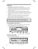
Page 6: ...ck technology keeps time date and settings during power outages and auto adjusts for Daylight Saving Time and Leap Years Display and print 1 12 AM PM or 24 Hour format Print time in regular minutes 00...

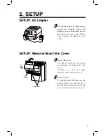
Page 7: ...Then plug the AC adapter into AC outlet SETUP Remove Attach the Cover 1 2 Remove the cover 1 Pull the top of the cover toward you supporting the bottom side of the cover 2 Pull it to front and upper d...

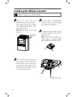
Page 8: ...three seconds Then display will change as follows and a ribbon cassette moves to the replacement position Note Ribbon cassette is not factory installed When you replace an installed ribbon cassette t...

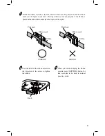
Page 9: ...n is placed behind the ribbon mask see the figure on the right When you finish changing the ribbon cassette press SETTING button for three seconds to be back to normal punching mode Turn the knob of t...

Page 10: ...nstall wall mount screws supplied into a wall 10 cm 3 15 16 apart Be sure to keep about 3 mm 1 8 of the screw head out of the wall Use template on the bottom of the back side of this manual if you pre...

Page 11: ...loyee may use new card number every pay period Employee inserts card into top of time clock for each punch 700E will automatically pull in the card print punch in proper positon print total hours if a...

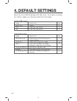
Page 12: ...Page DATE TIME Settings Modes Pay Period Print Format Max In 15 17 18 Calculating mode with weekly pay period starting on Monday AM PM hours minutes date English Auto Break Deduction 20 Do not automa...

Page 13: ...ay hours is the format that the hours appear on the clock face Once you select AM PM for display hours time in setting mode is also indicated in AM PM format Setting the Time Below image shows an exam...

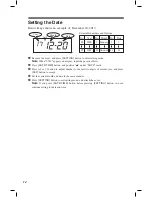
Page 14: ...or button to adjust number to the last two digits of current year and press SET button to accept Set the current month and date in the same manner Press SETTING button to exit setting mode and attach...

Page 15: ...lating Semi Monthly Pay Period Option MODE 1 2 3 4 Monthly once per month Weekly ever 7 days Bi Weekly every 14 days Semi Monthly twice per month Calculating Calculating Calculating Calculating 6 7 8...

Page 16: ...y period Options 4 or 9 Option 1st Starting Date Semi monthly only MODE Starting Date Day 1 31 Date of month Starting Date No Monthly Pay Period 1 2 3 4 Sunday Monday Tuesday Wednesday 5 6 7 Thursday...

Page 17: ...and press SET button to accept accept Press SETTING button to exit setting mode and attach the cover Note If you press FUNCTION button before pressing SETTING button you can continue setting for funct...

Page 18: ...Option You can allow employees to override the Max in option using the Out buttons on the front of clock if they occasionally work shifts longer than the Max In setting For example if Max In is set at...

Page 19: ...g mode and attach the cover Note If you press FUNCTION button before pressing SETTING button you can continue setting for function Hour 12AM 11PM No 0 23 No 00 59 Minute 00 59 Selectable numbers and O...

Page 20: ...feature You must set a base working elapsed time and break duration Once total working hours reaches to Elapsed Time Break Duration will be deducted from the total working hours For example if you ha...

Page 21: ...h and the time OUT punch and then it calculates the hours from the time IN punch and the time OUT punch When rounding the time IN punch it will raise the fractions that occur and for the rounding of t...

Page 22: ...te breakpoint quarter hour The following is an example of 15 minute rounding with a 7 minute breakpoint IN Punch Rounding OUT Punch Rounding 0 3 9 5 1 9 7 Min B P 7 Min 7 Min Rounds To 9 30 Achtal Pau...

Page 23: ...ay ber 201 If set as the above the unit remembers the starting date as the Sunday of March and the ending date as the t Sunday of ber Once set the unit automatically updates the settings every year th...

Page 24: ...or button to select number of ending date in the same manner and press SET button to accept Press SETTING button to exit setting mode and attach the cover Note If you press FUNCTION button before pres...

Page 25: ...se that you ve already set a passcode 9999 appears on display You need to input the current passcode first to change the passcode No passcode is set by default Select a number for the first digit of y...

Page 26: ...ment Note Any setting shall be kept After you press a RESET switch date and time is shown on the display RESET BUTTON Hour Minute Mo Date All settings including weekly programs will be deleted when th...

Page 27: ...nd time at the current time RESET BUTTON Press these 2 buttons at the same time Hour Minute SA AM To return all settings to their factory default All settings will be deleted and will revert to the fa...

Page 28: ...a password has been set You ll need to input the password first See pg 23 for inputting the password 3 Use the or buttons to move through the registered card numbers When you find the card number you...

Page 29: ...number you want to delete or select ALL to delete all cards registered to the recorder Press SET to confirm 3 Use the or buttons to move through the registered card numbers and select ALL Press SET 4...

Page 30: ...word you set 4 digit numbers Correctly set the starting date and ending date of the daylight saving time Check the setting contents and input the correct figures CPU Error The remaining life of lithiu...

Page 31: ...ime card is inserted straight into the unit If improper printing still remains after checking above points contact the store from whom you bought the unit 99 99 appears when you try to enter the setti...

Page 32: ...hours after the date of shipment Temperature 5 C to 45 C 23 F to 113 F Humidity 20 to 80 RH no condensation Approx 3 5lbs 1 6 kg with AC adapter 6 7 8 w x 9 5 8 h x 5 3 16 d 175 w x 244 h x 132 d mm T...

Page 33: ...or shock hazards Do not damage break or modify the power cord Do not put a heavy object on pull or forcefully bend the cord either These may damage the cord possibly resulting in a fire or electric sh...

Page 34: ...ord may be damaged possibly leading to a fire or electric shock Remove the line cord plug from the outlet before transferring the unit or it may damage the cord possibly leading to a fire or electric...

Page 35: ...aid Lathem will not assume any responsibility for any loss or damage incurred in shipping 6 WARRANTY DISCLAIMER AND LIMITATION OF LIABILITY Except only the limited express warranty set forth above the...

Page 36: ...Level Line Wall Mount Template Leave about 1 8 gap between wall and screw head Holes should be 3 15 16 or 10 cm apart...

Reviews: