background image

LT-3100 User & Installation Manual Rev. 1.06 


Interfaces 

Lars Thrane A/S 

www.thrane.eu 

Page 30 of 155 

The SIM card will be delivered from the Iridium Service Provider (ISP) together with the essential 
information: 


MSISDN number (the Iridium voice number) 


ICC-ID 


PIN codes 


PUK codes 

The SIM card will be delivered with the SIM lock feature disabled. Thus, the LT-3100 system will be 
operational as soon as the SIM card is inserted. 

If the user decides to activate the SIM lock function from the UI display, then the PIN code is required next 
time the LT-3100 system is powered up. Change of the SIM card PIN code can only be performed, if the PIN 
lock is enabled. If changing the SIM card PIN code, then the SIM card default PIN code cannot be restored, 
and the new PIN code must be used to unlock the SIM card and the Iridium services. 


Ethernet RJ45 (LAN)


The LT-3110 Control Unit has an Ethernet LAN (RJ-45) interface, currently supporting service & 
maintenance. The Ethernet interface must be used to access the built-in web server, which is further 
described in 

Web server

 on page 100.  

The LT-3110 Control Unit will automatically request and obtain an IP address when connected to a Local 
Area Network (LAN) with a DHCP server (e.g. a router). If connecting the LT-3110 Control Unit directly to a 
PC, the two will automatically negotiate an IPv4 Link-Local address. The current IP address can be found in 
the user interface display (Menu -> System -> Network: IP Address). 


Summary of Contents for LT-3100

Page 1: ...User Installation Manual LT 3100 Satellite Communications System Document Number 95 100765 Rev 1 06 Release date January 2022 Copyright Lars Thrane A S Denmark ALL RIGHTS RESERVED...

Page 2: ......

Page 3: ...S Lars Thrane A S is not responsible for the content or accuracy of any translations or reproductions in whole or in part of this manual from any other source Copyright 2022 Lars Thrane A S All rights...

Page 4: ...the main power switch is on WARNING Use only the supplied cable Use only the supplied power and communication cable for connecting the equipment WARNING Permanent watch In case of smoke or water leaks...

Page 5: ...terference to radio communications However there is no guarantee that interference will not occur in a particular installation If this equipment does cause harmful interference to radio or television...

Page 6: ...m The manual is primarily intended for installers and service personnel Personnel installing or servicing the system should be professionals with technical expertise properly trained and likewise auth...

Page 7: ...sed for new installations of the LT 3100 System and should be updated to ensure the best possible performance of the system and services NOTE The latest LT 3100 Software and Release Notes can always b...

Page 8: ...y Instructions for Installer Operator July 13 2018 CT 1 04 As a result of the FCC certification process the following sections are updated Safety Instructions for Installer Operator November 5 2018 CT...

Page 9: ...acket Mount 1 5 to 2 5 pipe Antenna Unit 19 Pole Mount 1 5 pipe 38 8 mm Antenna Unit 23 Pole Mount 2 0 pipe 53 0 mm Antenna Unit 25 Interfaces 27 LT 3110 Control Unit 27 LT 3130 Antenna Unit 36 Power...

Page 10: ...ystem 88 Bridge Alert Management BAM 93 Serial Interface RS 422 97 GNSS sentences 97 BAM sentences 98 NMEA 0183 over UDP 99 Web server 100 Accessing the built in web server 101 Dashboard 102 Messages...

Page 11: ...Mount Control Unit 147 App J Outline Drawing Flush Mount Control Unit 148 App K Outline Drawing LT 3130 Antenna Unit 149 App L Outline Drawing Pole Mount 1 5 pipe 38 8mm Antenna Unit 150 App M Outlin...

Page 12: ...maritime satellite communication equipment The LT 3100 system has voice and data capabilities with 100 global coverage provided by the Iridium Communications Network The LT 3100 system consists of a...

Page 13: ...installed according to manufacturer s User Installation Manual The LT 3100 system includes an integrated Global Navigation Satellite System GNSS receiver for position fixing The LT 3130 Antenna Unit o...

Page 14: ...mounted using the bracket or pole mount delivered by Lars Thrane A S The antenna unit mounts are listed with part numbers P N in Accessories on page 4 Inspection Inspect the shipping cartons and or wo...

Page 15: ...of the basic system and must be ordered separately 91 100768 Aux Cable 3m 91 101183 Coaxial cable 4 9mm 10m 91 101184 Coaxial cable 4 9mm 25m 91 101137 Coaxial Cable 10 3mm 10m 91 101138 Coaxial Cable...

Page 16: ...product which is using the Iridium satellite constellation The LT 3100 system is working on the new Iridium NEXT satellites An overview of the LT 3100 system is illustrated in Figure 1 The LT 3100 sys...

Page 17: ...ifications in App G Specifications on page 145 The LT 3110 Control Unit has the following interfaces 4 pin power connector male marked PWR Chassis ground connector marked GNDC N connector female for c...

Page 18: ...gure 4 and Figure 5 The Flush Mount Control Unit is not included in the LT 3100 Satellite Communications System Basic P N 90 101142 and must be ordered separately Mounting and installation considerati...

Page 19: ...nstallation and Mounting Lars Thrane A S www thrane eu Page 8 of 155 The Bracket Mount and Flush Mount for the LT 3110 Control Unit are illustrated in Figure 4 and Figure 5 Figure 4 Bracket Mount Cont...

Page 20: ...2 m The LT 3120 Handset is designed for indoor mounting Check the specifications in App G Specifications on page 145 The LT 3120 Handset has the following characteristics High performance audio speak...

Page 21: ...120 Handset The LT 3121 Cradle specifications are available in App G Specifications on page 145 IMPORTANT The LT 3121 Cradle contains a magnet to hold on to the LT 3120 Handset Make sure that other el...

Page 22: ...e display see Figure 43 on page 43 Mount the unit on a rigid structure with a minimum of exposure to vibration and shock Mount the unit using either the Bracket Mount or Pole Mount provided by Lars Th...

Page 23: ...coaxial cable N connector male to the antenna unit The coaxial cable N connector thread nut must be fastened by hand only IMPORTANT Maximum allowed torque is 2 Nm when connecting the coaxial cable N c...

Page 24: ...in Figure 12 WARNING The safety distance from the LT 3130 Antenna Unit is 0 1 m 0 3 ft in order to comply with the regional regulations IMPORTANT Due to the adjacency of the Iridium and Inmarsat frequ...

Page 25: ...Unit must be obeyed Figure 13 is illustrating how the LT 3130 Antenna Unit should be mounted to avoid interference from radars IMPORTANT Failing to obey the specified installation conditions will void...

Page 26: ...a 360 clear view of the sky However minor obstructions such as a mast will not degrade the antenna performance severely if a separation distance larger than 15 times the diameter of the obstruction i...

Page 27: ...e 2 NOTE The LT 3130 Antenna Unit must be mounted with a 22 clear view angle below the horizontal plan port and starboard directions where no obstructions must block the Iridium satellite signal to ma...

Page 28: ...nder extreme pitch conditions Also the upper hemisphere must be without any blockages to the Iridium satellites IMPORTANT For best possible performance of the LT 3100 system the LT 3130 Antenna Unit m...

Page 29: ...be mounted below the Inmarsat C antenna with a minimum distance of 1 m and below an angle of minimum 15 when coexistence is required Practical use of the LT 3100 system during Alpha and Beta Sea trial...

Page 30: ...over time The Cable Hose can be ordered separately from Lars Thrane A S on the following P N 91 102470 Cable Hose standalone The Cable Hose incl installation steps is more detailed illustrated in doc...

Page 31: ...Antenna Unit N connector 4 Apply self volcanic tape on the N connector and cable to protect against saltwater and corrosion or use the recommended Cable Hose NOTE Always fasten the Bracket Mount Ante...

Page 32: ...5 to 2 5 pipe Antenna Unit can support pipes in the interval 1 5 to 2 5 The torques are specified in Figure 22 The bracket mount V bolts and nuts are all made of A4 stainless steel Figure 21 Bracket...

Page 33: ...pe and an aluminum anodized thread block which can be fastened to the LT 3130 Antenna Unit providing protection to the coaxial cable N connector and surroundings NOTE The cable hose will be included i...

Page 34: ...le to protect against saltwater and corrosion 4 Screw the pole mount clockwise on the LT 3130 Antenna Unit and fasten the antenna lock pinot screw as illustrated in Figure 27 max torque 1 2 Nm 5 The L...

Page 35: ...Mount 1 5 pipe Antenna Unit only supports a 1 5 pipe The pinot screws antenna and pole lock torques are specified in Figure 26 and Figure 27 The pole mount is made of milled aluminum anodized The pin...

Page 36: ...o protect against saltwater and corrosion 4 Screw the pole mount clockwise on the LT 3130 Antenna Unit and fasten the antenna lock pinot screw as illustrated in Figure 30 max torque 1 2 Nm 5 The LT 31...

Page 37: ...ipe 53 0mm Antenna Unit only supports a 2 0 pipe The pinot screws antenna and pole lock torques are specified in Figure 29 and Figure 30 The pole mount is made of milled aluminum anodized The pinot sc...

Page 38: ...standards minimum is compliance to IEC 60945 2002 When extending the power supply cables the positive and the negative must be installed closely together in order to keep the cable inductance low NOT...

Page 39: ...tion Manual Rev 1 06 Interfaces Lars Thrane A S www thrane eu Page 28 of 155 Chassis ground The chassis ground connector is placed on the back side of the LT 3110 Control Unit and marked with GNDC see...

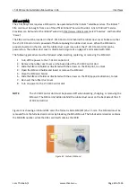
Page 40: ...ust be followed when inserting replacing or removing the SIM card 1 Turn off the power to the LT 3110 Control Unit 2 Remove the rubber dust cover on the back side of the LT 3110 Control Unit 3 Slide t...

Page 41: ...ormed if the PIN lock is enabled If changing the SIM card PIN code then the SIM card default PIN code cannot be restored and the new PIN code must be used to unlock the SIM card and the Iridium servic...

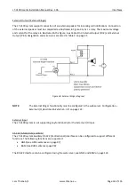
Page 42: ...le 3m is an accessory part and must be acquired separately The LT 3110 Control Unit is supporting external ringer functionality on the Auxiliary External I O interface which can be configured from the...

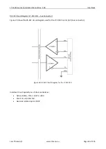
Page 43: ...it Diagram LT 3110 CU Aux Connector Figure 35 shows the RS 422 circuit diagram used for the LT 3110 Control Unit Aux connector Interface Drive Capability as a Talker and Listener A Rx B Rx Y Tx 60V to...

Page 44: ...signation and wire colors are listed in Table 3 on page 31 NOTE The External Ringer functionality must be configured in the web server Configuration External I O described in External I O on page 123...

Page 45: ...has a N Connector male for the interface to the LT 3130 Antenna Unit The N Connector interface is providing data communication and power to the antenna unit over a coaxial cable The N connector marked...

Page 46: ...of 155 Bluetooth The LT 3110 Control Unit has built in Bluetooth 4 0 with integrated antenna providing wireless communication between Bluetooth capable devices and the LT 3100 system Max Power RF Tx...

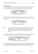
Page 47: ...iding enough information about the DC resistance in which cases the cable manufacture must be approached to obtain this information Lars Thrane A S has calculated the maximum allowed cable lengths wit...

Page 48: ...respected and calculate the maximum cable length as a function of the input voltage and the total DC resistance Contact Lars Thrane A S to get assistance on selection and acceptance of a specific coa...

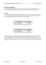
Page 49: ...activated only when the 24 VDC input power source is available The coaxial cable length is an adding factor to the total power consumption of the system A short coaxial cable will add approximately 0...

Page 50: ...ich must be followed LT 3110 Control Unit back view with an upscaled power connector are illustrated in Figure 37 The Chassis ground GNDC must be connected sufficiently to the vessel ground 91 102218...

Page 51: ...wo units It is important that the coaxial cable connected to both the LT 3110 Control Unit and LT 3130 Antenna Unit is not grounded in any of the ends Do not connect the coaxial cable shield to vessel...

Page 52: ...r the LT 3100 system The galvanic isolated power supply must be used to protect the LT 3100 AC DC Galvanic Isolated Power Supply Connection of an AC DC galvanic isolated power supply is illustrated in...

Page 53: ...e dialled number is available in the display or a contact is selected in the Contacts or Call History The off hook button can also be used to accept an incoming call The alternative to use the off hoo...

Page 54: ...rated in Figure 43 Status bar view area and soft keys The essential system status and system notifications are shown in the status bar which is always present The view area contains the active view Th...

Page 55: ...than one active icon the slot will continuously take turn showing one icon at a time for a few seconds before cycling to the icon of the next function Time Position Slot 7 6 5 4 3 2 1 Figure 44 LT 311...

Page 56: ...an unspecified error There is an active data connection Data service unavailable due to an unspecified error Table 11 LT 3110 Control Unit UI Iridium service Notifications Slot 3 There are one or mor...

Page 57: ...etters will be in lower case The numeric keypad can be used to enter text All letters will be in upper case Table 14 LT 3110 Control Unit UI input mode Miscellaneous Functions Slot 6 A Bluetooth devic...

Page 58: ...Figure 45 The main menu is represented by three sub menus Phone Settings and System The three sub menus are listed in Table 17 Figure 45 LT 3110 Control Unit UI display main menu Sub menus Entries Pho...

Page 59: ...Page 48 of 155 The main menu is represented by three submenus Phone Settings and System The three submenus are listed in Table 17 Figure 46 Phone submenu Figure 47 Settings submenu Figure 48 System s...

Page 60: ...em installation and mounting is described in the previous sections IMPORTANT In order for the LT 3100 system to be deemed operational and ready for continuous service i it must be correctly installed...

Page 61: ...a SIM Card An Iridium SIM card must be used for activating a LT 3100 system The SIM card is described and illustrated in SIM card SIM on page 29 The SIM card may be acquired directly from your Lars T...

Page 62: ...LT 3100 system or any other Iridium activated product Use the following link https www iridium com who is my sp You can use the following information ICCID SIM card serial number MSISDN Mobile Subscr...

Page 63: ...SP see Activating the System on page 49 Change of Hardware Hardware Procedure Comments LT 3110 Control Unit The LT 3110 CU can be replaced by swapping the hardware Remember the SIM card from the old L...

Page 64: ...he Lars Thrane Image LTI file e g LT 3100 v1 13R 00XX lti will include all software components to all system units All system units connected to the LT 3110 Control Unit will be upgraded or downgraded...

Page 65: ...tem is supporting connection of external SIP phones The connection of external SIP phones is described in External SIP Phones on page 65 The LT 3100 system is supporting Mobile Originated MO outgoing...

Page 66: ...count the user can lift the handset out of the cradle The example in this section shows how to use the off hook button identifying an entry in the Contacts and initiate the voice call by pressing the...

Page 67: ...of the cradle It is always possible to mute and unmute the microphone in the handset from the LT 3110 Control Unit soft key Mute and Unmute when having an active call and the handset is lifted out of...

Page 68: ...the on hook mode described in the previous section NOTE The LT 3100 system will provide the user with information while connecting and throughout the voice call In case of problems with the satellite...

Page 69: ...ng number up against the Contacts entries if a match exists the name of the contact will be showed for the incoming voice call Figure 59 Incoming Voice Call 1 of 3 Figure 60 Incoming Voice Call 2 of 3...

Page 70: ...missed voice call is illustrated in the above figures By highlighting the missed call in the Call History and press the off hook button the LT 3100 system will start establishing a voice call to the...

Page 71: ...If sending an Email to the LT 3100 system then leave the Subject field empty Please note that all text larger than an SMS 160 characters is truncated and that the length of the Email address one chara...

Page 72: ...phoner number Email address when entries are available Figure 66 to Figure 72 illustrates sending a new SMS to a normal phone number NOTE If the Contact has a Phone Number and an Email address the use...

Page 73: ...from Sending to Sent when the SMS has successfully been sent from the LT 3100 system see Figure 71 and Figure 72 Figure 69 Sending SMS 4 of 7 Figure 70 Sending SMS 5 of 7 Figure 71 Sending SMS 6 of 7...

Page 74: ...ol in the status bar a notification tone and the soft key SMS 1 will be shown as illustrated in Figure 73 To read the incoming SMS press the softkey SMS 1 or navigate to the Phone submenu MENU Phone S...

Page 75: ...Services Lars Thrane A S www thrane eu Page 64 of 155 NOTE The LT 3100 system is handling SMS conversions which is grouped based on the recipient s address NOTE SMS and Email can also be sent from th...

Page 76: ...The SIP phone might require a DHCP Server to get an IP address assigned Depending on network setup it might be needed to configure DHCP Server mode in the LT 3100 system The LT 3110 Control Unit UI di...

Page 77: ...alling between the SIP phones and the LT 3120 Handset The number plan is illustrated in Table 20 The Caller ID is defined by the user when configuring the SIP phones NOTE The LT 3100 system is only su...

Page 78: ...ing an Analogue Phone Adapter Configuration of Grandstream HT802 Adapter example If you would like to connect the Analogue Phone Adapter directly to the LT 3100 system then it might help you to insert...

Page 79: ...nterface RJ45 connector Access to the serial interface from a PC requires a virtual COM or tty port driver supporting RFC 2217 e g the Serial Port Redirector from Fabulatech on Windows and ttynvt on M...

Page 80: ...ction The user of the LT 3100 system must confirm the termination of the Modem Data connection by pressing the soft key Yes The LT 3100 system is supporting most of the AT command set supported by the...

Page 81: ...stalled on a PC and use the Serial over Ethernet RFC 2217 e g SPR Virtual COM port to establish a Modem Data connection RUDICS to a dedicated RUDICS server Table 22 list several Email programs and com...

Page 82: ...in the web server then a tracking symbol will be shown in the status bar of the LT 3110 Control Unit display Also this is to inform the user that tracking reports will be sent periodically The user of...

Page 83: ...4 hours whatever is first triggered time or distance If Time and or Distance trigger have been enabled then Mode is set to Periodic If none of these trigger conditions have been enabled then Mode is...

Page 84: ...is possible to edit the body text with optional information to the recipient of the vessel position Whenever the recipient address and body text are completed use the Navigation key to enter the body...

Page 85: ...ork emulate an ethernet connection to connected devices Applications running on connected devices will see the connection as through ethernet due to this simulation The PAN profile is currently the on...

Page 86: ...ed under Known Devices at the bottom of the Bluetooth submenu this is displayed on Figure 91 To disconnect the device from the LT 3100 the user can either disable Bluetooth on the LT 3110 Control Unit...

Page 87: ...LT 3100 User Installation Manual Rev 1 06 System Services Lars Thrane A S www thrane eu Page 76 of 155 Figure 92 Bluetooth How to pair 5 of 5 The device has been disconnected and forgotten...

Page 88: ...ft key New and add phone number and or Email and name The phone number is limited to numbers e g 004529401008 The Contact list can contain 100 contacts Use international number prefix either or 00XX i...

Page 89: ...vides a complete list of all voice calls outgoing incoming and missed calls as illustrated in Figure 96 Unknown entries in the Call History will show the soft key New Contact to help creating the Unkn...

Page 90: ...ge The Phone Usage lists Trip and Lifetime user terminal usage The list includes voice totals for incoming and outgoing voice calls data incoming and outgoing and SBD sent and received To switch betwe...

Page 91: ...Installation Manual Rev 1 06 System Submenus Lars Thrane A S www thrane eu Page 80 of 155 Figure 100 Phone submenu Phone Usage Figure 101 Phone submenu Phone Usage Phone Usage MENU Phone Phone Usage L...

Page 92: ...Settings submenu contains the following entries Audio Display Date Time Phone Setup Bluetooth Security and Reset Options See Figure 102 and Figure 103 for the layout of the Settings submenu Figure 10...

Page 93: ...3120 Handset speaker user audio The user can adjust the Handset Volume during a voice call by using the LT 3120 Handset volume button up down on the side of the handset Ringer Volume adjusts the outp...

Page 94: ...the brightness whereas long press on the Brightness button changes between day and night time Date Time Date Time settings provides the user with a possibility to change formats after completing the...

Page 95: ...Note that these numbers are not dialable from this menu Bluetooth The Bluetooth submenu offers the user the ability to wirelessly connect devices to the LT 3100 using Bluetooth How to setup this conne...

Page 96: ...s required as seen on Figure 112 To change the SIM PIN the user is required to input the current SIM PIN and then select a new SIM PIN The New SIM PIN must be repeated before it is confirmed See Figur...

Page 97: ...To change SIM PIN the SIM Lock feature has to be enabled NOTE There is a minimum requirement of four digits for new SIM PIN s There is however no max limit of digits Figure 114 Settings submenu Secur...

Page 98: ...Figure 116 and Figure 117 NOTE The reset of the web server authentication can be managed from the Settings submenu for the user to get access to the web server in the situation where the user cannot...

Page 99: ...erview of the active alerts in the LT 3100 system The Bridge Alert Management BAM is described and illustrated in detail in Bridge Alert Management BAM on page 93 NOTE The BAM Alerts list illustrated...

Page 100: ...lerts 3 of 4 Figure 124 BAM Alerts 4 of 4 BAM alert shown in the status bar active warning The blue dot indicates a change in the BAM Alerts after the user has last been in the list Long press on the...

Page 101: ...illustrated in Figure 125 NOTE Use the IP Address to access the built in web server Instructions to access the built in web server is provided in Accessing the built in web server on page 101 Tracking...

Page 102: ...SS receiver status in Automatic GNSS mode The Manual Position input will not be shown in the Position Status window The Position Status Automatic GNSS integrity states are further described and illust...

Page 103: ...ne number IMEI mobile equipment number and ICCID SIM card number The System Info is illustrated in Figure 128 and in Figure 129 Power Supply The Power Supply provides details about the DC input voltag...

Page 104: ...evant alerts The user can at any time check for the presence of alerts without performing any action if there are one or more active alerts a BAM icon representing the alert with the highest priority...

Page 105: ...ary consideration of the situation or of given information The shape and color of the BAM icon indicates the priority of the alert and the symbol inside indicates its state as per Table 24 below BAM A...

Page 106: ...e user To acknowledge an alert press the ACK Alert soft key Some alerts cannot be acknowledged by the user in which case the ACK Alert soft key will be absent This applies to alerts for which the aler...

Page 107: ...alert the CAM system may apply responsibility transfer and raising a new alert with if practicable a lower priority NOTE Alerts of priority caution are not audible and therefore cannot have their res...

Page 108: ...the LT 3100 system The configuration of the GNSS sentences are illustrated and described in GNSS and BAM on page 124 IMPORTANT The GNSS receiver of the LT 3100 system is not certified according to IM...

Page 109: ...the LT 3100 system Table 26 presents the supported BAM sentences by the LT 3100 system The configuration of the BAM sentences is illustrated and described in GNSS and BAM on page 124 NOTE The encodin...

Page 110: ...tination address will be 192 168 1 255 The UDP destination port is user configurable see Table 27 The configuration of the NMEA 0183 over UDP is illustrated in section GNSS and BAM on page 124 The Tal...

Page 111: ...o where the PC is connected NOTE The IP address allocated to the LT 3110 Control Unit is shown in the GUI Menu System Network IP Address The functionality of all web pages is described in further deta...

Page 112: ...ress The IP address is valid if the Link Status is showing Up The IP address is assigned dynamically by a DHCP server 3 From the PC start a browser e g Microsoft Edge Explorer Chrome etc and type in t...

Page 113: ...e on the web server dashboard as illustrated in Figure 139 Otherwise only the control unit will be visible For each unit the following information will be available unit number unit name unit part num...

Page 114: ...ng on the individual Email the message will expand and the user can read the content of the message Reading an Email on the Web server clears the SMS notification on the LT 3110 Control Unit To compos...

Page 115: ...expand and the user can read the content of the message Reading an SMS on the Web server clears the SMS notification on the LT 3110 Control Unit To compose an SMS either click the Compose SMS field o...

Page 116: ...as been properly performed the system is fully operational In this section there will be a description of system settings which are configurable from the Web Server Under Configuration the following w...

Page 117: ...tem changes the default password during the installation of the system so that a random user on the network do not have access to the web server If the authentication password is changed from default...

Page 118: ...lso able to download the diagnostics file The operator needs to login using the Admin profile to set a password for the User profile this is displayed on Figure 146 After setting the User profile pass...

Page 119: ...Page 108 of 155 NOTE It is recommended that the installer of the LT 3100 system sets the User profile password during the installation of the system It is highly recommended to keep the User profile p...

Page 120: ...nfiguration modes will be described in this section DHCP client DHCP server Static The default network configuration mode for the Ethernet interface is DHCP client NOTE In DHCP client mode Link local...

Page 121: ...which are documented in Table 28 IMPORTANT Do not connect the LT 3100 System to any external IP networks which are not trusted The LT 3110 Control Unit has Firewall rules configured on all Ethernet po...

Page 122: ...r is offered for assigning IP addresses to network clients The web server DHCP server mode setting is illustrated in Figure 150 NOTE A user scenario for configuration the DHCP server mode is when e g...

Page 123: ...nit must never change Typically used if connecting the LT 3110 Control Unit to an IP network where a DHCP server is already available and where it is important that the IP address assigned for the LT...

Page 124: ...The LT 3100 system is currently only supporting the Bluetooth profile Personal Area Network PAN the Headset profile is not supported It is possible to enable the Bluetooth transceiver and change the d...

Page 125: ...services are described in Data Modem Data SMS and SBD on page 68 By activating Enable serial over network the LT 3110 Control Unit will give access to the AT command interface port 5020 on the IP add...

Page 126: ...3110 Control Unit UI display MENU System SIP Phones it is possible to get an actual status of the number of SIP devices and their registration status This is further illustrated and described in Syste...

Page 127: ...page 77 It is possible to both edit and create new contacts The web server contact list is identical to the one seen on the LT 3110 Control Unit To add a new contact press the sign then input Name Pho...

Page 128: ...ion The tracking transport types and report formats currently supported in the LT 3100 system are summarized in Table 29 Figure 156 Web server Tracking Transport Types Report Formats Transport Type Re...

Page 129: ...t when both requirements have been met maximum every 1 hour If the speed over ground is than 5 knots then a tracking report will be sent every 5 0 NM If the speed over ground is 5 knots then a trackin...

Page 130: ...ust be provided The Iridium Service Provider will configure the SBD subscription and server routing all SBD messages related to this IMEI number to a specific address e g Email address of the tracking...

Page 131: ...ormats Thrane text and Human readable Be aware that sending many tracking reports via SMS will not be the most affordable configuration The format of a tracking report SMS Human readable sent to e g a...

Page 132: ...0 The Email tracking is supporting two formats Thrane text and Human readable The format of a tracking report Email Thrane text sent to an Email address is illustrated in Figure 161 Figure 160 Web ser...

Page 133: ...agement must be enabled by the user and a password must be chosen as illustrated on Figure 162 The Remote Management is using the SMS service as communication layer The Tracking Remote Management func...

Page 134: ...r The AUX connector is described in Auxiliary AUX on page 31 Figure 163 is illustrating the configuration of the External I O Output The External I O output configuration options are listed in Table 3...

Page 135: ...ite systems e g GPS only this can be managed under the GNSS module as illustrated in Figure 164 It is possible to configure the following functionality GNSS and BAM on the LT 3110 Control Unit CU AUX...

Page 136: ...gure 165 IMPORTANT The installation of the LT 3130 Antenna Unit will affect the performance of the GNSS receiver If line of sight to the GNSS satellites are disturbing the quality of the signal receiv...

Page 137: ...ation GNSS and BAM The baud rate can be configured to 4 800 9 600 or 38 400 baud The output rate of the NMEA 0183 sentences is 1 Hz Figure 166 below shows the NMEA 0183 sentences supported by the LT 3...

Page 138: ...ail in Auxiliary AUX on page 31 BAM must be enabled via the web server under Configuration GNSS and BAM The baud rate can be configured to 4 800 9 600 or 38 400 baud For BAM configuration see Figure 1...

Page 139: ...g Contact List Call History SMS etc The LT 3100 system will reboot once the factory reset has been affected NOTE Using Reset to factory default the LT 3100 system will lose all settings configured and...

Page 140: ...Report contains data describing the current state of the system and historical events The data can be used by support to identify issues and determine their cause To help identifying a potential prob...

Page 141: ...tware image will take a few minutes Progress indication bars can be monitored on the Software update webpage while the software update is on going The LT 3100 system will reboot once the software imag...

Page 142: ...tion login where it is required to use the Username and Password to re enter the web server again The Authentication is described in Authentication on page 106 Disable login timeout The web server wil...

Page 143: ...numbers identified The unit part numbers and the unit serial numbers are identified on the unit label which is found on the backside or at the bottom side of the units Alternatively use the built in...

Page 144: ...Maritime navigation and radiocommunication equipment and systems Bridge alert management Part 1 Operational and performance requirements methods of testing and required test results 2 IEC 62923 2 Mari...

Page 145: ...ic SIM No Responsible for managing the Subscriber Identity Module SIM card It is not possible to deactivate this function Table 35 Alert generating functions Category Description A Alert for which add...

Page 146: ...Resp transfer Yes Title Lost antenna Can ACK Yes Transitory No Description Iridium service unavailable Check antenna cable What to do Check the cable between the Control Unit and the Antenna Unit Cond...

Page 147: ...Priority Warning Category B Resp transfer Yes Title Invalid antenna Can ACK Yes Transitory No Description Incompatible antenna What to do Replace the Antenna Unit with a compatible one HW revision 2...

Page 148: ...3100 system currently supports IEC 61162 over RS 422 only but is prepared for future support of IEC 61162 over Ethernet Certification of compliance with IEC 61162 450 and IEC 61162 460 has been obtai...

Page 149: ...No listener sentences available for GNSS GNSS Talker Identification Mnemonics Talker Device Identifier Function Global Navigation Satellite System GNSS GN GNSS Global Positioning System GPS GP GNSS GL...

Page 150: ...LT 3100 system can transmit as a talker BAM Listener sentences overview The table below lists all sentences the LT 3100 system can receive as a listener BAM Talker Identification Mnemonics Talker Dev...

Page 151: ...es Automatic GNSS State UTC POSN POSN age Horizontal Accuracy COG SOG kts Comments System has just booted and there is not yet a fix Acquiring Acquiring System booting up System has just booted and on...

Page 152: ...eu Page 141 of 155 System has just booted and there is not yet a fix System has just booted and only time is known Figure 173 GNSS Receiver Integrity State Figure 174 GNSS Receiver Integrity State Fi...

Page 153: ...S www thrane eu Page 142 of 155 Horizontal accuracy 50 m SOG 0 kts Horizontal accuracy 50 m SOG 0 kts Figure 177 GNSS Receiver Integrity State Figure 178 GNSS Receiver Integrity State Figure 179 GNSS...

Page 154: ...www thrane eu Page 143 of 155 SOG 1 m s 2 kts GNSS fix completely lost last known position has age 10 min Figure 181 GNSS Receiver Integrity State Figure 182 GNSS Receiver Integrity State Figure 183 G...

Page 155: ...5 GNSS fix completely lost last known position has age 23 hours 59 min GNSS fix completely lost last known position has age 24 hours Figure 185 GNSS Receiver Integrity State Figure 186 GNSS Receiver I...

Page 156: ...bands 12 24 VDC 10mW TX 2402 2480MHz RX 2402 2480MHz Compass Safe Distance std Compass Safe Distance steer 0 60 m 2 0 ft 0 40 m 1 3 ft LT 3120 Handset Weight 290 g 0 64 lbs Dimensions 208 8 x 52 8 x...

Page 157: ...LT 3100 User Installation Manual Rev 1 06 Appendixes Lars Thrane A S www thrane eu Page 146 of 155 App H Outline Drawing LT 3110 Control Unit Figure 189 Outline Drawing LT 3110 Control Unit...

Page 158: ...T 3100 User Installation Manual Rev 1 06 Appendixes Lars Thrane A S www thrane eu Page 147 of 155 App I Outline Drawing Bracket Mount Control Unit Figure 190 Outline Drawing Bracket Mount Control Unit...

Page 159: ...LT 3100 User Installation Manual Rev 1 06 Appendixes Lars Thrane A S www thrane eu Page 148 of 155 App J Outline Drawing Flush Mount Control Unit Figure 191 Outline Drawing Flush Mount Control Unit...

Page 160: ...LT 3100 User Installation Manual Rev 1 06 Appendixes Lars Thrane A S www thrane eu Page 149 of 155 App K Outline Drawing LT 3130 Antenna Unit Figure 192 Outline Drawing LT 3130 Antenna Unit...

Page 161: ...of 155 App L Outline Drawing Pole Mount 1 5 pipe 38 8mm Antenna Unit NOTE The Pole Mount 1 5 pipe Antenna Unit interfaces to a pipe of maximum 1 5 38 1 mm measured outer diameter The total weight of t...

Page 162: ...p M Outline Drawing Pole Mount 2 0 pipe 53 0 mm Antenna Unit NOTE The Pole Mount 2 0 pipe 53 0 mm Antenna Unit interfaces to a pipe of maximum 2 0 53 0 mm measured outer diameter The total weight of t...

Page 163: ...t 1 5 to 2 5 pipe Antenna Unit interfaces to a pipe of maximum 2 5 63 5 mm measured outer diameter The total weight of the Bracket Mount is 714 g 1 57 lbs A Cable Hose must be used with the Bracket Mo...

Page 164: ...LT 3100 User Installation Manual Rev 1 06 Appendixes Lars Thrane A S www thrane eu Page 153 of 155 App O Outline Drawing LT 3120 Handset Figure 196 Outline Drawing LT 3120 Handset...

Page 165: ...LT 3100 User Installation Manual Rev 1 06 Appendixes Lars Thrane A S www thrane eu Page 154 of 155 App P Outline Drawing LT 3121 Cradle Figure 197 Outline Drawing LT 3121 Cradle...

Page 166: ...LT 3100 User Installation Manual Rev 1 06 Appendixes Lars Thrane A S www thrane eu Page 155 of 155 App Q EU Declaration of Conformity...

Page 167: ...Lars Thrane A S Skovlytoften 33 2840 Holte Denmark www thrane eu...

Reviews: