LT-3100 User & Installation Manual Rev. 1.06
Installation and Mounting
Lars Thrane A/S
www.thrane.eu
Page 11 of 155
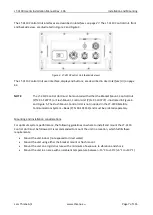
LT-3130 Antenna Unit
The LT-3130 Antenna Unit is designed for outdoor mounting and connected to the LT-3110 Control Unit via
a coaxial cable. The LT-3130 Antenna Unit specifications are available in
on page 145.
The LT-3130 Antenna Unit has an N connector (female) mounted, centered at the bottom of the antenna.
Mounting and installation considerations:
•
Mount the unit vertically (with the N connector pointing down)
•
Mount the unit with free line of sight to the Iridium® and GNSS satellites. Make sure that the unit
can receive signals from the Iridium® and GNSS satellites (satellite reception information is
available in the LT-3110 Control Unit user interface display, see Figure 43 on page 43)
•
Mount the unit on a rigid structure with a minimum of exposure to vibration and shock
•
Mount the unit using either the Bracket Mount or Pole Mount provided by Lars Thrane A/S
•
Mount the unit outdoor with an ambient temperature between -40°C to +55°C (-40°F to +131°F)
•
Mount the unit with a minimum angle of 20 degrees towards a radar antenna (above or below) and
keep a minimum distance of 2.5 m (8 ft)
•
Mount the unit at least 1 m. (3 ft.) away from radio transmitting antennas (VHF, UHF, MF-HF)
•
Mount the unit away from Inmarsat and transmitting VSAT antennas
NOTE
:
It is only the LT-3130 Antenna Unit marked with HVIN 2.00 (Unit Label) or newer that can
be used for the LT-3100 Satellite Communications System. The LT-3100 software will check
the antenna unit during power up and the system will not be operational, if connecting a
legacy LT-3130 Antenna Unit.
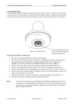
Figure 10: LT-3130 Antenna Unit.
The LT-3130 Antenna Unit has
an N connector (female) at the
bottom side of the unit.
Summary of Contents for LT-3100
Page 2: ......
Page 167: ...Lars Thrane A S Skovlytoften 33 2840 Holte Denmark www thrane eu...


