3: DSM Installation
3: DSM Installation
DSM Installation consists of mounting the DSM in a 19” rack and making network and
power connections.
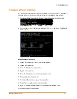
You connect a VGA and keyboard, or laptop, configure network settings, then log in to
the DSM WebManager interface to complete the final setup and configuration steps.
To configure the initial network settings for the DSM, you connect to the unit with either a
VGA and keyboard connection or a serial connection to a laptop or other terminal.
If you choose to connect using the serial console (VGA and keyboard), your serial
connection should be configured as follows:
Baud Rate
115200
Data Bits
8
Parity
None
Stop Bits
1
Flow Control None
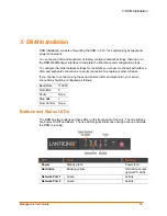
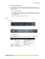
Buttons and Status LEDs
The DSM has two buttons and five LEDs on the front panel of the unit. The two buttons
are Power On/Off and Reset. The five LEDs signal information during boot-up and while
the DSM is running.
LED
State
Meaning
Power
Steady green
Power is on.
Hard drive access
(typical PC LED).
Hard drive
Blinking yellow
Network Port 1
Green
Activity.
Network Port 2
Green
Activity.
ManageLinx User Guide
12


