background image

12

Motherboard Information

Chapter 3

Network Application Platforms


T

he controller contains two modes of operation—a 

legacy  mode  using  I/O  space,  and  an  AHCI  mode 
using  memory  space.  Software  that  uses  legacy 
mode will not have AHCI capabilities.


The  AHCI  (  Advanced  Host  Controller  Interface)  is  a 

programming  interface  which  defines  transactions 

between  the  SATA  controller  and  software  and 

enables  advanced  performance  and  usability  with 

SATA. Platforms supporting AHCI may take advantage 

of  performance  features  such  as  no  master/slave 

designation for SATA devices—each device is treated 

as a master—and hardware assisted native command 

queuing. AHCI also provides usability enhancements 

such as Hot-Plug. Here is the list of the AHCI capabilities 

which exist in the system:

Hardware assisted native command queuing

1. 

Aggressive power management

2. 

LED indicator support

3. 

Note: 

To  configure  your  hard  disk  as  AHCI 

compatible,  use  the  BIOS  menu.  Refer  to 

IDE 

Configuration  Settings

  on

  Chapter  4 

BIOS  Settings

Also, Intel(R) Matrix Storage Manager (for use on 

systems  using  Intel(R)  82801HBM  I/O  Controller 

Hub  (ICH8M)-  AHCI  only)  has  to  be  installed,  for 

more  information,


visit  http://downloadcenter.

intel.com/Detail_Desc.aspx?lang=eng&chan

geLang=true&DwnldId=19607

Serial Interface Connectors(J9)

:  It is for connecting the 

RS-232 serial port module cable. This is COM2 where 

as the external console port (RJ45) is COM1.

SPI-ROM Update Connector (J3)

 Using the appropriate 

cable to connect this 10-pin ISP pin header connector, 

the user can update the SPI Flash soldered on board. 

LPC  I/O  bus  (Port  80  output  for  Debug  Card)  (J4)

It  is  Intel  proprietary  connector  for  connecting  a 

checkpoint device to output checkpoints throughout 

bootblock and Power-On Self Test (POST) to indicate 

the task the system is currently running. 

SIM  Card  Tray  (CN5)

:  It  is  for  connecting  SIM  card  for 

mobile Internet connection. 

Mini-PCIe Socket(CN6)

: It is for connecting WiFi module 

to  serve  Wireless  LAN  connections  or  connecting 

Wireless 3G module for mobile Internet connections. 

The  socket  is  provided  through  the  Universal  Serial 

Bus (USB) 2.0 host interface.

USB Connector(USB 2 and 3, J11) 

: It is for connecting 

the USB module cable. It complies with USB2.0 and  

is capable of low-speed, full-speed, and high-speed  

which    can  support  up  to  480  Mbps  connection 

speed.

Function

Pin No.

Data Carrier 

Detected

1

Received Data

3

Transmitted 

Data

5

Data Terminal 

Ready

7

Signal Ground

9

Pin No.

Function

2

Data Set Ready

4

Request to 

Send

6

Clear to Send

8

Ring Indicator

10

Signal Ground

1
3
5
7
9

2
4
6
8

10

Pin No.

Function

2

NC

4

V_3P3_SPI

6

SPI_HOLD0_L

8

SPI_ICH_CLK

10

SPI_ICH_

MOSI

Function

Pin No.

NC

1

SPI_CS0

3

SPI_ICH_MISO

5

KEY

7

GND

9

2

4
6
8

10

1
3
5
7
9

Pin No.

Function

9

LPC_AD2

7

LPC_AD3

5

LPC_FRAME_N

3

RST_80DGPT_N

1

CLK_33M_P80

Pin No.

Function

10

GND

8

GND

6

+3.3V

4

LPC_LAD0

2

LPC_LAD1

10

8
6
4
2

9
7
5
3
1

1    

3    

5   

9

2

4

10

Function

Pin No.

USB_VCC

1

Key

3

USBD0-

5

USBD0+

7

Ground

9

Pin No.

Function

2

Ground

4

USBD1+

6

USBD1-

8

Key

10 USB_VCC

Summary of Contents for FW-7541

Page 1: ...Network Application Platforms Hardware platforms for next generation networking infrastructure FW 7541 User s Manual Publication date 2012 08 01...

Page 2: ...Compliances CE This product has passed the CE test for environmental specifications Test conditions for passing included the equipment being operated within an industrial enclosure In order to protec...

Page 3: ...rmittent failures Be sure to follow ESD prevention procedures when removing and replacing components to avoid these problems Wear an ESD preventive wrist strap ensuring that it makes good skin contact...

Page 4: ...ard 6 Installing 3G SIM Card 7 Installing Wireless 3G Module 7 Mounting 7 Tabletop Mounting 7 Rack Mounting 7 Chapter 3 Motherboard Information 9 Block Diagram 9 Motherboard Layout 10 Jumper Settings...

Page 5: ...40 Appendix D Programming LAN Bypass 41 Appendix E Driver Installation 42 LAN Adapters Driver Installation 42 On the Windows OS 42 On Linux 43 VGA Driver Installation 44 On the Windows OS 44 On Linux...

Page 6: ...2 5 SATA HDD and CompactFlash for storage All of the above mentioned are packed into a small rugged unit 268mmx40mmx145mm 10 55 x1 57 x5 71 Please refer to the chart below for a summary of the system...

Page 7: ...ied with systems shipped without pre installed hard disks including the following items ESD protection pad to cover the exposed screws from hard disk installation Hard disk mounting screws Hard disk a...

Page 8: ...bit LAN ports Left LED If the LED is green it indicates that the connection speed is 100Mbps If the LED is orange it indicates that the connection speed is 1000Mbps Right LED If the LED is on it indic...

Page 9: ...for about 3 seconds to reboot the system without turning off the power R2 Power on Switch It is a switch to turn on or off the power R3 AC Power in socket The system requires a 60W 12V switching powe...

Page 10: ...er is removed Unscrew the 6 screws from the top cover of the FW 1 7541 System Open the cover 2 Installing the System Memory The motherboard supports DDR3 memory that features data transfer rates of 66...

Page 11: ...o cover the exposed screws for ESD protection Connect the Serial ATA cables to the HDD 5 Plug the Serial ATA drive and power cables to the 6 Serial ATA drive and the 4 Pin Serial ATA Power connectors...

Page 12: ...or multi unit rack assembly the operating ambient temperature of the rack environment may be greater than room ambient Therefore consideration should be given to installing the equipment in an enviro...

Page 13: ...hreaded oval head screws provided to the rack mounting bracket Make sure that the power adaptor socket is not blocked by the aligning holder in the front You could use the cable holder to hold your ca...

Page 14: ...figure for your motherboard s layout design 1x DDR3 667 800Mhz SO DIMM X4 DMI Intel 82583V Intel 82574L Intel 82583V Intel 82583V Intel 82583V Intel 82583V 6x PCI E x1 VGA Up to 4GB MAX 2 x SATA II US...

Page 15: ...nments and the internal connectors Ethernet Ports USB2 0 Ports Console Port USB 2 and 3 Connectors Mini PCI E Connector VGA Interface SO DIMM Socket SATA 1 2 Con nectors Serial Port Connector Keyboard...

Page 16: ...CPU and system fans monitored temperature and speed under the menu of Hardware Health Configuration You could also configure the target temperature to adjust the fan speed automatically VGA Interface...

Page 17: ...PI ROM Update Connector J3 Using the appropriate cable to connect this 10 pin ISP pin header connector the user can update the SPI Flash soldered on board LPC I O bus Port 80 output for Debug Card J4...

Page 18: ...ty please contact us either through the sales rep or technical support Note For the update version of the BIOS image please visit Lanner s support page at http assist lannerinc com Then select support...

Page 19: ...ons from the available options using the navigation keys Note This manual describes the standard look of the setup screen There may be some instances in which the motherboard features can vary from on...

Page 20: ...On the other hand Options in blue can be modified The right frame displays the key legend Above the key legend is an area reserved for a text message When an option is selected in the left frame it i...

Page 21: ...z Cache L1 Cache L2 This specifies the size of the Level 1 and Level 2 caches in Kilobytes Ratio Actual Value This shows the actual CPU ratio MAX CPUID Value Limit The CPUID tells the OS BIOS what the...

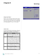
Page 22: ...ect options for the IDE Configuration Settings Use the up and down Arrow keys to select an item Use the Plus and Minus keys to change the value of the selected option A description of the selected ite...

Page 23: ...o SetthisvaluetoallowtheBIOStoautomatically detect the IDE disk drive type attached to the specified channel This setting should be used if an IDE hard disk drive is attached to the specified channel...

Page 24: ...is value if the IDE disk drive support cannot be determined This is the default setting 0 Set this value to allow the BIOS to use PIO mode 0 It has a data transfer rate of 3 3 MBs 1 Set this value to...

Page 25: ...UDMA3 Set this value to allow the BIOS to use Ultra DMA mode 3 It has a data transfer rate of 44 4 MBs To use this mode it is required that an 80 conductor ATA cable is used UDMA4 Set this value to al...

Page 26: ...ing Enabled Set this value to prevent the hard disk drive from being erased IDE DetectTime Out Seconds Set this option to stop the AMIBIOS from searching for IDE devices within the specified number of...

Page 27: ...e IDE bus for IDE disk drives in 35 seconds ATA PI 80 Pin Cable Detection Set this option to specify the Ultra ATA80 cable detection method Option Description Host Choose this value to use the IDE con...

Page 28: ...to Disabled the serial port physically becomes unavailable 3F8 IRQ4 Set this value to allow the serial port to use 3F8 as its I O port address and IRQ 4 for the interrupt address Thisisthedefaultsett...

Page 29: ...rityof serial port 1 or COM1 ports on computer systems use IRQ4 and I O Port 3F8 as the standard setting Themostcommonserialdeviceconnectedtothis port is a mouse If the system will not use a serial de...

Page 30: ...ports on computer systems use IRQ7 and I O Port 378H as the standard setting 278 Set this value to allow the parallel port to use 278 as its I O port address 3BC Set this value to allow the parallel...

Page 31: ...tart running if the fan is not yet turned on And the system fan can also be turned off automatically if the temperature for the system is at or below the specified value Refer to Motherboard Layout on...

Page 32: ...re described on the following pages The screen is shown at right Remote Access You can disable or enable the BIOS remote access feature here Option Description Disabled Set this value to prevent the B...

Page 33: ...ond of the serial port Note The external console port RJ45 is com1 whereas the serial interface connector J9 is com2 Redirection After BIOS POST A terminal emulation program such as HyperTerminal runn...

Page 34: ...ating systems OS e g Windows ME 98 NT and MS DOS Normally if this option is not enabled any attached USB mouse or USB keyboard will not become available until a USB compatible operating system is full...

Page 35: ...0 30 40 Sec the BIOS will wait for up to 10 20 30 40 seconds for the USB flash drive to initialize Emulation Type USB Emulation refers the system being able to boot to a USB drive Normally if this opt...

Page 36: ...or Port 1 and Port 2 You can activate or deactivate the Lan Bypass ports For the description of the physical ports that are capable of the LAN Bypass function refer to the Front Panel Feature in Chapt...

Page 37: ...he BIOS to skip some power on self tests POST while booting to decrease the time needed to boot the system When set to Disabled BIOS performs the complete series of tests Select Enabled or Disabled to...

Page 38: ...rt up sequence even when an error is detected Hit DEL Message Display When this item is set to Enabled the system displays the message Press DEL to run Setup during the start up sequence Interrupt 19...

Page 39: ...a Supervisor and a User password If you use both passwords the Supervisor password must be set first The system can be configured so that all users must enter a password every time the system boots o...

Page 40: ...e sub menu You can use the sub menu to change the supervisor password Change User Password Select this option and press Enter to access the sub menu You can use the sub menu to change the user passwor...

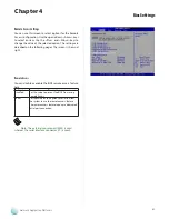
Page 41: ...stem to select the Emulation type for a USB drive Option Description Auto Setthisvaluetoallowthesystemtoautomatically detect a USB drive emulation type Floppy Set this value to allow the system to sel...

Page 42: ...overed from a power outage Option Description Power Off When setting to Power Off the system goes into off state after an AC power interruption Power On When setting to Power on the system turns on au...

Page 43: ...essor s reset signal is asserted Thus the processor will be restarted as if a human operator had cycled the power For sample watchdog code see watchdog folder on the Driver and Manual CD To program th...

Page 44: ...ings in the BIOS Setup 2 menu for the device Please refer to the Remote Access Settings on Chapter 4 BIOS Settings BIOS Advanced Remote Access Configuration Serial Port Mode 115200 8 n 1 Configure Con...

Page 45: ...excution Function Clear_LCM This Function is Clear the LCD Module Direct write the function to your program Read_KeyPad ThisFunctiongettheKeyPadnumberifuserpressed key Direct write function to your pr...

Page 46: ...Disabled Enabled PWR ON Bypass Non Bypass PWR OFF Bypass Bypass Bypass settings System Status LAN Bypass for Port1 and Port 2 LAN Bypass 1 2 when power off Enabled Disabled Disabled PWR ON Non Bypass...

Page 47: ...Intel PRO Network Connections InstallShield Wizard window appears Select the I accept the terms in the license agreement 6 and then click Next Select the programs that you wish to install Make sure 7...

Page 48: ...by typing the following 5 command make install The binary will be installed as 6 lib modules kernel_version kernel drivers net e1000 o The install locations listed above are the default locations They...

Page 49: ...eries processors an integrated graphics processing unit GPU is included which implement the Integrated Intel Graphics Media Accelerator 3150 You could visit the Intel support website for the VGA drive...

Page 50: ...ll be returned at customer s expense The following conditions are excluded from this 5 warranty Improper or inadequate maintenance by the customer Unauthorized modification misuse or reversed engineer...

Page 51: ...ing by Air Freight Sea Express ___ Others ________________ Item Model Name Serial Number Configuration Item Problem Code Failure Status Problem Code 01 D O A 02 Second Time R M A 03 CMOS Data Lost 04...

Reviews: