background image

LW 300 E / LW 450 E 
 

Page A - 62 

A


M A I N T E N A N C E   A N D   S E R V I C E  

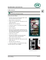
Safety valves 

Every pressure stage is equipped with a separate over pressu-
re safety valve. Safety Valves avoid a non permissible high 
pressure at the specific pressure stages and limit maximum 
operation pressure of the compressor. 

 
Safety valves are adjusted to: 

•  1st Stage: 8 bar 

•  2nd Stage: 50 bar 

•  3rd Stage: max. final pressure 


The adjusted blow-off pressure [bar] of the safety valves is 
indicated on their housings. 

All safety valves are factory sealed with special L&W safety 
seals to avoid manipulation of the limit value settings. 

Safety valves with removed seals have to be immediately che-
cked for the prescribed settings and replaced if necessary. 

The safety valve of the final stage is furthermore equipped 
with a knurled screw to be activated once. 

Turning the knurled screw clockwise could vent the valve 
completely and therefore the final filter housing. 

During normal operation conditions, the knurled screw has to 
be turned anti-clockwise up to the upper stop. An integrated 
circlip avoids complete unscrewing. 

If a safety valve blows off, it indicates problems with either 
inlet or outlet valve of the following stage. 

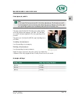
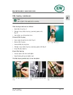
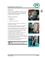
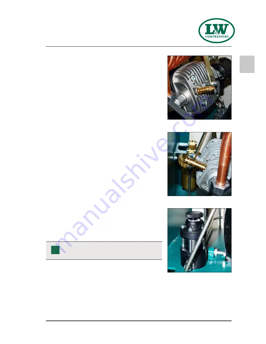
Safety valve 1st stage 

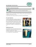
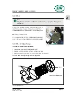
Safety valve 2nd stage 

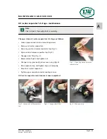
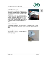
Safety valve 3rd stage 

Note 

Replace defective safety valves immediately! 

 
Version: 261012-001 E 

Summary of Contents for LW 300 E

Page 1: ...A Operating Instructions Breathing Air Compressor LW 300 E LW 450 E www uebler net Version 11 12 E ...

Page 2: ...on instructions Safety regulations 16 Locating the unit Installation in closed rooms 18 Dimensions 19 Minimum distances 20 Ventilation 21 Electrical Installation 22 23 Operation Important operation instructions 25 First commissioning 26 28 Daily commissioning 29 Filling procedure 30 Switch off the compressor 31 Remedying faults 32 36 Maintenance and Service Service Repair and Maintenance 38 Mainte...

Page 3: ...ge 54 Filter cartridge change 55 Filter housing Maintenance 56 Inlet filters Inlet filter cartridge change 57 Cylinder heads and valves 58 Replace inlet and outlet valves 1st and 2nd stage 59 60 Replacement inlet and outlet valves 3rd stage 61 Safety valves 62 Pressure maintaining non return valve 63 Safety valve test 64 Leak test 65 Pressure gas vessel test 66 Maintenance records 67 72 Storage Co...

Page 4: ...s is excluded from warranty and liability for this product Carry out other commissioning steps only if you have fully understood the following contents Before commissioning and using the unit carry out all the essential preliminary work and measures concerning legal regulations and safety These are described on the following pages of this operati on manual G E N E R A L I N F O R M A T I O N Note ...

Page 5: ...o shut down Oil temperature display with auto shut down Puracon filter monitoring ECC control in remote control box Additional high pressure outlet Direction of rotation monitoring Power cable and plug Automatic condensate drain Automatic stop at final pressure Hour counter Start Stop and emergency stop switch con densate test buttons Motor protection switch emergency stop switch Pressure maintain...

Page 6: ...hing Air Intake Pressure atmospheric atmospheric Oil Pressure bar 2 0 2 0 Oil Capacity l 2 2 2 2 Intake Temperature C 0 45 0 45 Ambient Temperature C 5 45 5 45 Cooling Air Volume m h 3 300 3 300 Voltage 400 V 3 phase 50 Hz 400 V 3 phase 50 Hz Protection Class Drive Motor IP 54 IP 54 Drive Power kW 7 5 11 RPM Motor min 1 2 890 2 890 Start Star Delta Star Delta Noise level dB A 82 from a distance of...

Page 7: ...00 E LW 450 E Page A 7 A Unit Assembly D E S C R I P T I O N No Designation 1 Filling pressure gauge 2 Switchboard 3 Filling hoses optional without filling hoses 4 Filling valves 1 2 Version 260912 001 4 3 ...

Page 8: ...LW 300 E LW 450 E Page A 8 A Switchboard D E S C R I P T I O N 1 2 3 4 5 No Designation 1 Emergency shut off switch 2 Hour counter 3 ON button 4 OFF button 5 Drain test button Version 261012 001 E ...

Page 9: ...e 13 Öl Wasserabscheider Oil Water Separator 14 3 Verdichterstufe 3rd Pressure Stage 15 Kondensatablassschlauch Condensate Release Hose 16 Sicherheitsventil 3 Stufe Safety Valve 3rd Stage 17 Wärmetauscher Heat Exchanger 18 Öl Wasserabscheider Oil Water Separator 19 Pneum Kondensatventil Pneumatic Condensate Valve 20 Magnetventil Solenoid Valve 21 Kondensatabscheider Endstufe Condensate Separator 2...

Page 10: ...A S A F E T Y P R E C A U T I O N S ...

Page 11: ... is complied with and inspection and maintenance requirements are en forced No change and modification to the unit can be made without the written agreement of the manu facturer The manufacturer is not liable for damage to persons or property resulting from unauthori sed modifications Operators Target groups in these instructions Operators Operators are persons who are authorized and briefed for t...

Page 12: ... on the unit Importance of notes and warning signs that are affixed to the compressor according to the applica tion or its equipment S A F E T Y P R E C A U T I O N S Warning High voltage Note Ensure correct direction of rotation Version 261012 001 E ...

Page 13: ...y with all local and national rules and regulations associated with this product Only trained and competent personnel are permitted to inspect repair and service the product Only authentic L W parts and accessories may be used for maintenance work Otherwise the proper functioning of the product may be impaired Do not use faulty or incomplete products Do not modify the product Inform L W in the eve...

Page 14: ...e is only taken into operation under safe and functional conditions Only operate the compressor if all protective and safety equipment e g detachable protective equipment are provided and in good working order Check the compressor at least once per day for obvious damage and defects Inform the respon sible department person immediately if anything is not as is should be including operation per for...

Page 15: ...n the main switch The machine and especially the connections and fittings should be cleaned from oil fuel and maintenance products at the beginning of the maintenance repair Do not use aggressive clea ning agents Use fibre free cleaning cloths Switch off compressor and clean with a slightly damp cloth Remove dirt from cooling pipes by using a brush After cleaning examine all pipes for leaks loose ...

Page 16: ...ork under suspended loads Also separate from minor relocation machinery system of any external energy supply Before recommissioning reconnect the machine to the mains according to regulations When recommissioning proceed according to the operating instructions Safety regulations Inspections according to legal and local obligatory regulations regarding accident prevention are carried out by the man...

Page 17: ...A LO C A T I N G T H E U N I T ...

Page 18: ...hat the compressor fan can intake fresh air from outside Ensure adequate ventilation and exhaust air opening When locating the compressor in rooms of less than 30 m space where natural ventilation is not ensured or other systems having high radiation are operating in the same room measures must be taken to provide artificial ventilation Intake air must be free from noxious gas e g smoke solvent va...

Page 19: ...LW 300 E LW 450 E Page A 19 A L O C A T I N G T H E U N I T Version 261012 001 E Dimensions 494 600 1040 1140 997 1317 Fig Dimensions ...

Page 20: ...lable To prevent serious damage ensure that the cooling air flow can flow freely The following minimum distances must be adhered Front side min 1500 mm sides min 500 mm rear side min 500 mm Avoid anything in this area which can restrict the cooling air flow Version 291112 001 E Fig Minimum distances 500 500 500 1500 Note Minimum distances must be adhered i ...

Page 21: ...an flow freely The necessary cooling air flow can be calculated by using the following formula 300 x drive power kW required cooling air flow m h Example 11kW motor 300 x 11kW 3300 m h required cooling air flow The fan capacity for fresh air and warm air must meet at least the required cooling air flow The fans must have the same capacity Version 291112 001 E Fig Ventilation through facade Fig Ven...

Page 22: ...or The fusing should be done in accordance with the valid regulations of the responsible electricity supply company When connecting the unit to the electrical supply check the compressor direction of rotation see chapter Maintenance Check turning direction Fuse the motor correctly see table use slow blow fuses Warning Work on the electrical equipment on with the machine unit may only be carried ou...

Page 23: ...ominal motor power Fusing start A Connection in mm kw A Direct Star Delta Contactorsupply Motor S D 2 2 5 10 1 5 1 5 4 8 5 20 2 5 1 5 5 5 11 3 25 20 2 5 1 5 7 5 15 2 30 25 2 5 1 5 11 21 7 35 4 2 5 15 29 9 35 6 4 18 5 36 50 6 4 22 41 50 10 4 30 55 63 10 6 Recommended fuses for 220 240 V operating voltage Nominal motor power Fusing start A Connection in mm kw A Direct Star Delta Contactorsupply Moto...

Page 24: ...A O P E R AT I O N ...

Page 25: ...Important operation instructions Note Ensure that all persons handling the compressor are familiar with function and operation of the unit i Wear hearing protection When working on a running machine always wear hearing protection Version 261012 001 E ...

Page 26: ...ntact an authorised electrician 3 Check oil pressure if oil pressure gauge is installed 4 Run the compressor for about 2 minutes 5 Close the open filling valve carefully 6 Run the compressor up to maximum pressure and check if the final pressure switch shuts off the compressor If the final pressure switch does not shut off switch off the compressor with the OFF button see chapter REMEDYING FAULTS ...

Page 27: ...lose tension during transportation Please check the V belt tension before starting the compressor Tension V belt To tighten V belt tension loosen 4 mounting nuts of the drive motor Use the tensioning screw to move the electric motor until the V belt tension is sufficient Then tighten mounting nuts and check V belt tension We recommend using a V belt tension gauge Correct V belt tension Do not tens...

Page 28: ...otation is wrong the guide pistons of the 2nd and 3rd stages can not be sufficiently lubricated with the consequence that the pistons will be damaged Further more cooling air flow will not be sufficient Rotation direction arrow Warning Wrong impeller rotation direction Immediately after switching the compressor on check rotation direction Depending on the place of installation the phase sequence c...

Page 29: ... I N G Prior to daily operation observe the following Ensure cooling air can flow freely Check compressor oil level by the oil sight glass Check if filter cartridge is in place observe filter cartridge life Ensure toxic free pure intake air Version 261012 001 E ...

Page 30: ...last test date are rated for the final pressure are free from humidity i 1 Close all filling valves 2 Connect the closed compressed air cylinders 3 Open cylinder valves 4 Start compressor by pushing the ON button 5 When the filling pressure gauge increases open the filling valves slowly 6 Fill compressed air cylinders to the desired pressure subsequently close the filling valves slowly 7 Close and...

Page 31: ...ts down the system when the corresponding final pressure is reached During filling process you can shut down the system at any time by pushing the red button OFF or the emergency stop only in case of emergency Note After automatic or manual switching off all pressure vessels and filter housings of the compressor will be automatically vented i Version 261012 001 E ...

Page 32: ...A R E M E D Y I N G FA U LT S ...

Page 33: ...es heat exchanger broken Replace Condensate drain valves leaky Unscrew valves check sealing surfaces clean replace if necessary Final pressure switch stop unit Verify settings replace if necessary Piston of pneumatic condensate valve sticks Clean pneumatic condensate valve and restore function check replace o rings replace valve completely if necessary Air supply too low Cause of fault Remedy Inle...

Page 34: ... direction Ensure correct phase rotation observe rotation direction arrow Inlet and outlet valves contaminated defective Clean replace if necessary Safety valve leaks Cause of fault Remedy Inlet and outlet valves of the following pressure stage defective Clean replace if necessary Sinter filter of the following water separator blocked Replace Safety valve leaky Replace Oil taste in the air Cause o...

Page 35: ...are not as prescribed control pressure of pneumatic condensate valve too low Check corresponding inlet and outlet valve replace if necessary Piston sealing of pneumatic condensate valve contaminated used up Clean replace if necessary Timer relais defective Replace Timer relais settings not correct Adjust as prescribed Compressor stops before final pressure Cause of fault Remedy Final pressure swit...

Page 36: ...ly saturated before change Store filter cartridges properly dispose defective cartridges Cylinder s piston s or piston ring s defective Replace Operating temperature too high Ensure sufficient ventilation Oil consumption too high Cause of fault Remedy Cylinder s piston s or piston ring s defective Replace Compressor oil unsuitable Use prescribed oil quality Operating temperature too high Observe p...

Page 37: ...A M A I N T E N A N C E A N D S E R V I C E ...

Page 38: ... trained personnel This is necessary because all maintenance work can not be explained exactly and detailed in this manual Only use authentic spare parts for service work Danger Components under pressure such as hose ends can quickly come loose when manipula ted and can cause potentially fatal injuries due to the pressure surge Any work on system parts may only be performed in a pressure compensat...

Page 39: ... of final pressure switch Every 3 months or as required Maintenance work Type Quantity Order No Check Retorque all connections and bolts Annually Maintenance work Type Quantity Order No Oil change if less than 1000 operating hours 2 2 000001 Check opening pressure of final safety valve Clean coolers Clean all oil water separators if less than 500 operating hours Service intake filter depends on co...

Page 40: ... I N T E N A N C E A N D S E R V I C E Every 500 operating hours Maintenance work Type Quantity Order No Change intake filter 1 000170 Check pressure maintaining non return valve Check V belt tension and condition Version 261012 001 E ...

Page 41: ...stage 1 000184 2nd stage 1 000173 1st stage 1 001294 2nd stage 3 001272 Replace o ring of oil separator 1 001294 Replace silencer 1 000178 Replace sintered metal filter of oil separators 1 000184 Replace sintered metal filter of pneumatic con densate valve 1 000188 Clean oil sieve replace if necessary 1 000798 Oil change 2 2 000001 Replace o rings of the final filter housing 2 001287 Replace back ...

Page 42: ...kets of 1st 2nd and 3rd stage gasket 3 000240 o ring 1 001274 1st stage 1 000259 2nd stage 1 000256 3rd stage 1 000510 Upper gasket 1st 1 000257 Upper gasket 2nd 1 000254 Lower gasket 1st 1 000258 Lower gasket 2nd 1 000253 Replace oil intake hose 1 000376 Replace all inlet and outlet valves incl gaskets Replace needle bearings for conrod 2nd and 3rd stage 2 003836 Version 191212 001 E ...

Page 43: ...del and interval the service kits include parts such as O Rings Sinter Filter Inlet Filter V Belts Silencers In Outlet Valve Valve Seals and Compressor oil Service Kits Compressor Frequency Operating Hours Order No LW 300 E 50 Hz 1000 h 006718 LW 300 E 50 Hz 4000 h 006719 LW 450 E 50 Hz 1000 h 003841 LW 450 E 50 Hz 4000 h 003834 Compressor Frequency Operating Hours Order No LW 450 E 60 Hz 1000 h 0...

Page 44: ...crew to move the electric motor until the V belt tension is sufficient Then tighten mounting nuts and check V belt tension We recommend using a V belt tension gauge Correct V belt tension Do not tension V belt too tight This damages bearings of compressor and motor The V belt should only be tensioned until there is no noise caused by slipping during start Motor Type Initial Installation Operation ...

Page 45: ... drain hose with oil drain valve Oil sight glass Lubricating System Oil Pressure Switch Check oil level Check oil before each operation of the system The oil level should be between the middle and upper end of the oil sight glass Never start the compressor with a too low oil level Refill new compressor oil at least when the oil level reached the middle of the indicated area Warning Check oil level...

Page 46: ...a funnel Check oil level The oil level should be between the middle and upper end of the oil sight glass Screw oil fill port manually in and tighten with the adjustable wrench The oil change is now completed Maintenance intervals First oil change after 25 operating hours total hours All further changes after each 1 000 operating hours Oil and oil capacity Approx 2 200 ml synthetic compressor oil i...

Page 47: ...ace the gaskets Soak the gaskets with oil before placing respect mounting direction Be sure to position the arrow see Fig Pos 1 from the new oil sieve opposite to inlet and return ports of the pump see Fig Pos 2 Remount the cover with the 4 cover screws Tightening torque 4 5 8 N The oil sieve change is now completed Maintenance intervals We recommend cleaning or replacing the oil sieve every 1 000...

Page 48: ...ing cut out pressure Turn the adjusting screw anti clockwise Adjust the pressure switch in steps of a quarter turn Restart the compressor after every adjustment step to verify the actual cut out pressure Example settings Note Do not adjust the final pressure switch to the safety valve pressure The final pressure switch has to be adjusted to min 10 bar below the safety valve pressure Otherwise the ...

Page 49: ...witch box and activates the dump valves about every 15 minutes To release the complete condensate through the black plastic hoses we recommend using an 20 l container at least The drain noise can be kept to a minimum by using a silen cer Maintenance intervals We recommend to clean oil and water separators every 500 operating hours or at least once a year to check for corrosion damage and to replac...

Page 50: ... Fig 3 Reassemble all parts and tighten nut Change o ring previously grease new o ring Fig 4 Place separator top and tighten ring nut manually Mount oil water separators Tighten pipe connections and mounting screws Oil water separator maintenance is now completed Fig 1 Open ring nut and remove separator top M A I N T E N A N C E A N D S E R V I C E Fig 2 Loosen nut at the separator top Fig 4 Chang...

Page 51: ...hange o ring previously grease new o ring Fig 4 Place separator top and tighten manually Remove bottom part Fig 5 Change o ring previously grease new o ring Press in bottom part Mount oil water separators Tighten pipe connections and mounting screws The oil water separator maintenance is now completed Fig 1 Unscrew and remove filter top M A I N T E N A N C E A N D S E R V I C E Fig 3 Change sinter...

Page 52: ...move separator top Fig 1 Loosen nut at the separator top Change sinter filter Fig 2 Reassemble all parts and tighten nut Change o ring previously grease new o ring Fig 3 Place separator top and tighten ring nut manually Replace silencer Mount oil water separators Tighten pipe connections and mounting screws The oil water separator maintenance is now completed Fig 1 Loosen ring nut Fig 3 Change o r...

Page 53: ...connections and mounting screws Remove pneumatic condensate valve Loosen connection Fig 2 Change sinter filter Fig 3 Tighten horizontal screw Mount pneumatic condensate valve Tighten pipe connections and mounting screws Pneumatic condensate valve maintenance is now completed Fig 2 Loosen connection Fig 3 Change sinter filter Note Clean all parts thoroughly before assembly i Version 261012 001 E ...

Page 54: ...breathing air purification system Air is compressed up to 330 bar dried and odour and tasteless purified Oil residues are bounded The breathing air filter cartridge consists of a molecular sieve and activated carbon filter Cartridge capacity approx 1 7 l All breathing air filter cartridges are factory vacuum sealed We recommend unpacking the filter cartridges just before installation Filter cartri...

Page 55: ...packing of the new filter cartridge and place it with the filter tool in the filter housing Screw the new filter cartridge hand tight in by using the filter tool Screw the cover of the filter housing first manually in After it has been completely screwed in turn cover antic lockwise for 90 This avoids tightening of the cover due to vibration The filter cartridge change is now completed Fig 1 Unscr...

Page 56: ... Loosen pipe connections and nuts Fig 3 Remove filter housing Dismount filter housing base Change o ring and back up ring previously grease both Fig 4 Screw filter base tight in Mount filter housing Connect pipe connections and tighten Adjust holding clamp and tighten nuts The filter housing maintenance is now completed Fig 2 Change o ring and back up rings Fig 4 Change o ring and back up rings Fi...

Page 57: ...ry 1 000 working hours depending on pollution grade Inlet filter cartridge change Inlet filter cartridge change as follows Loosen cover by pushing the three clips apart Remove inlet filter cartridge and replace it by a new one Refit cover and snap the three clips until a loud click can be heard The inlet filter cartridge change is now completed Air filters Note Dirty filters make intaking air diff...

Page 58: ...t valve heads to change valves The three valves are combined inlet and outlet valves The first and second stage valves are plate valves The third stage con tains a spring operated piston which acts inside a bronze cylinder Maintenance intervals All valves should be replaced after 4 000 working hours due to normal wear and tear To replace valves the cylinder heads have to be removed There are no sp...

Page 59: ...s Loosen valve head screws Fig 1 Remove valve head Pull out inlet and outlet valve Fig 2 CAUTION Observe that the lower copper valve ring is also pulled out It can still stick inside the cylinder Check valve head if defective Install Inlet Outlet Valve see following page Fig 1 Loosen valve head screws Fig 2 Pull out inlet and outlet valve Note The figures of the parts can differ due to the differe...

Page 60: ...nlet and outlet valve CAUTION Observe the correct paper gasket position centre inlet and outlet channels Fig 4 Note Valve head screws can be inserted into the valve head to secure the upper valve gasket Refit the valve head and tighten the valve head screws cross wise Starting torques 1 nd Stage 45 Nm 2 nd Stage 30 Nm The replacement inlet and outlet valves 1st and 2nd stage is now completed Fig 3...

Page 61: ...tre pin Mount valve gasket on inlet and outlet valve CAUTION Ensure correct mounting position of the upper valve gasket Fig 4 Insert new inlet and outlet valve into valve head CAUTION Observe correct position between valve centre hole and valve head centre pin Place bottom valve gasket Place valve head with the new inlet and outlet valve Tighten valve head screws crosswise tightening torque 30 Nm ...

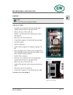
Page 62: ...lation of the limit value settings Safety valves with removed seals have to be immediately che cked for the prescribed settings and replaced if necessary The safety valve of the final stage is furthermore equipped with a knurled screw to be activated once Turning the knurled screw clockwise could vent the valve completely and therefore the final filter housing During normal operation conditions th...

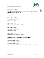
Page 63: ...valve prevents the compressed air from blowing off final pressure gauge 0 bar When the adjusted opening pressure is reached 150 and 180 bar the purified compressed air flows via pressure maintai ning and non return valve to the filling valve The value of the opening pressure of the pressure maintaining valve can be read at the final pressure gauge When opening pressure is reached the pressure gaug...

Page 64: ...the final pressure gauge The safety valve should open when reaching working pressure of the compressor If not switch off the unit and take out of service until the safety valve has been replaced Switch off the compressor Disconnect the compressor from the electrical power supply and protect against unexpected restart Remove the cover of the switch box Switch off the Test Safety Valve switch pressu...

Page 65: ...ff the compressor at a pressure of approx 150 bar Verify the compressor for release noises A slight hiss of the air inlet filter nozzle can be ignored If release noises occur localise blow off position s Switch off the compressor Disconnect the compressor from the electrical power supply and protect against unexpected restart Remove the cover of the switch box Switch off the leak test switch solen...

Page 66: ...s smaller than 999 result Test is applicable Example Filter housing 2 3 l Maximum operating pressure 350 bar Content volume 2 3 litres 350 bar x 2 3 litres 805 805 is smaller than 999 result Test is applicable Pressure gas vessels up to 999 have to be tested as follows 1 Examination after 5 years by a qualified person Visual inspection inside and outside 2 Examination after 10 years by a qualified...

Page 67: ...A M A I N T E N A N C E R E C O R D S ...

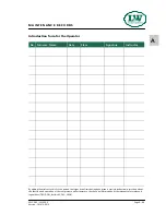
Page 68: ...e Signature Instructor By adding themselves to this list the person that signs it confirms having been given a yearly introduction instruction about the function and operation of the compressor unit Furthermore they have be informed about the relevant safety rules and regualtions TRG DGRL BetrSichV GSG GSGV Version 161012 001E ...

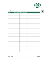
Page 69: ...LW 300 E LW 450 E Page A 69 A M A I N T E N A N C E R E C O R D S Top up oil oil change Date Operating hours Oil quantity l Name Version 161012 001E ...

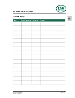
Page 70: ...LW 300 E LW 450 E Page A 70 A M A I N T E N A N C E R E C O R D S Cartridge change Date Operating hours Difference Name Version 161012 001E ...

Page 71: ...LW 300 E LW 450 E Page A 71 A M A I N T E N A N C E R E C O R D S Maintenance work Description Date signature Version 161012 001E ...

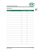
Page 72: ...LW 300 E LW 450 E Page A 72 A M A I N T E N A N C E R E C O R D S Replaced Parts Designation Part number Date signature Version 161012 001E ...

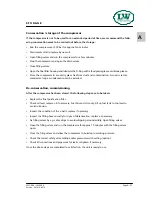
Page 73: ...vation commissioning After the compressor has been stored the following steps are to be taken Replace the final purification filter Check oil level replace oil if necessary Fuel Driven Units only Fill up fuel tank to top level to avoid corrosion Inspect the condition of the v belts replace if necessary Inspect the filling hoses visually for signs of deterioration replace as necessary Fix filling v...

Page 74: ...oceed according to the operating instructions Disposal The product must be disposed in accordance with national waste disposal regulations and by an appropriate waste disposal company Electric and electronic components EU wide regulations for the disposal of electric and electronic appliances which have been defined in the EU Directive 2002 96 EC and in national laws are effective from August 2005...

Reviews: