background image

1

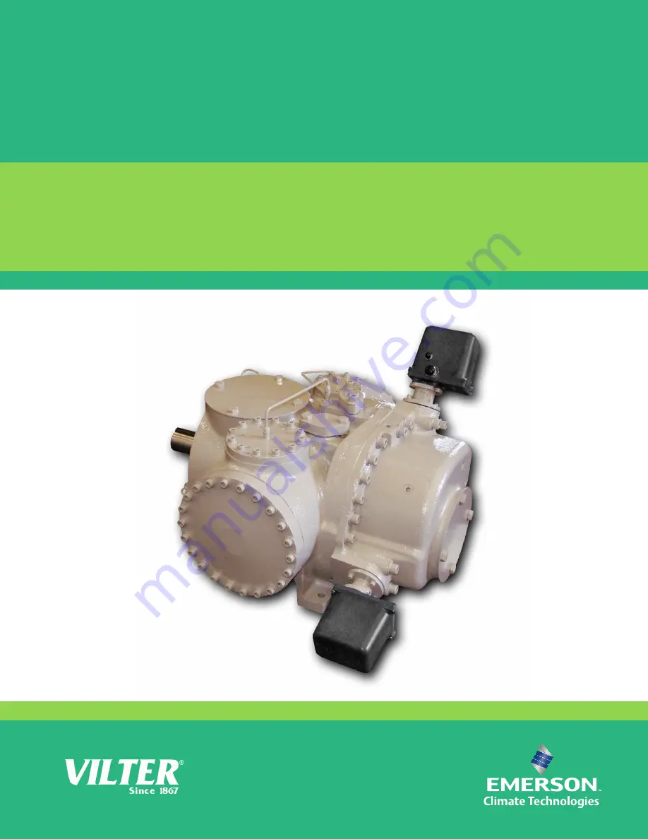
VSG & VSSG

Single Screw Bare Shaft Compressor

The World’s Best Compressors

For Gas Compression

TM

Summary of Contents for VSG

Page 1: ...1 VSG VSSG Single Screw Bare Shaft Compressor The World s Best Compressors For Gas Compression TM ...

Page 2: ...2 ...

Page 3: ...ment should be thoroughly inspected upon arrival Any damage noted should be reported immediately to the Transportation Company This way an authorized agent can examine the unit determine the extent of damage and take necessary steps to rectify the claim with no serious or costly delays At the same time the local Vilter representative or the home office should be notified of any claim made All inqu...

Page 4: ...4 ...

Page 5: ...e Shooting Guide 22 Operation Section 26 Notice on using Non Vilter Oils 26 Maintenance 29 Service 30 Parts Section 57 Gate Rotor 58 Shaft Seal 62 Tandem Shaft Seal 63 Main Rotor 64 Slide Valve Cross Shafts and End Plate 66 Slide Valve Carriage Assembly 68 Actuator Command Shaft 72 Miscellaneous Frame Components 74 Replacement Tools 78 VSG 301 701 Replacement Parts Section 81 Gaterotor Assembly 82...

Page 6: ...instructions This warranty does not apply i to ordinary wear and tear damage caused by corrosion misuse overloading neglect improper use or operation including without limitation operation beyond rated capacity substitution of parts not approved by Seller accident or alteration as determined by Seller or ii if the product is operated on a gas with an H2S level above 100 PPM In addition Seller does...

Page 7: ...nd replace inhibitors as necessary and check for signs of corrosion 4 Before leaving Vilter Manufacturing the compressor is evacuated and pressurized with dry nitrogen to 5 psig Pressure must be monitored with the gauge provided by Vilter and checked on a regular basis at least monthly 5 The rotor shaft must be rotated every 3 months to prevent flat spots from developing on the bearing surfaces an...

Page 8: ...ion of H2 S in the pro cess gas not exceed 100 PPM If H2 S is present in the process gas in any concentration special oil additives are required to protect the compressor from corrosion Notice on using Non Vilter Oils Oil and its additives are crucial in refrigeration system performance Vilter Manufacturing will NOT APPROVE non Vilter oils for use with Vilter compressors Due to the innumerable cho...

Page 9: ...ature etc Pressure Therearefourpressuretransducersrequiredtoread system pressures as listed below 1 Suction pressure transducer 15 0 300 PSIG measuresthegassuctionpressureintothecom pressor housing which provides the permissive to start for minimum suction pressure and is used for annunciation of low suction pressure while running and in the capacity control logic 2 Dischargepressuretransducer 15 ...

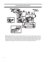
Page 10: ...hmotoramperage andisusedinthe capacity control logic The rotary potentiometers indicate the position of the slides which is used as a start ing permissive and in the capacity control logic Also additional input points may be required for customer connection of remote signals such as Start and Stop commands and capacity setpoint control MOTOR OPTIONAL REMOTE AIR COOLED OIL COOLER STANDARD WATER COO...

Page 11: ...ssrequirement andtoprevent the relief valve from opening 9 PrelubeOilPressure Thispointactsasapermissive to start the compressor and protects against the compressorstartingwithnooillubrication If during astartsequence theprelubeoilpressurefailstorise above4 0PSID thecompressorwillfailtostart The prelube oil pressure is a calculated value obtained by subtracting the discharge pressure reading from ...

Page 12: ...mum Allowable Working Pressure MAWP of the separator 5 Oil Prelube Pump Usually a direct driven gear typepump theoilpumpisrequiredtoprelubethecompres sorpriortostartingandtomaintainoilpressureduringany periods of low compression ratio operation 6 Oil Cooler Temperature Control Valve An oil cooler either air or water cooled must be used to remove the heat of compression from the oil stream A temper...

Page 13: ...th of the shafts while supporting the radial loads from the shafts The suction gas enters the compressor housing through the top inlet flange at the driven end of the unit The driven end of the compressor hous ing is flooded with gas at suction pressure The gas enters the open end of the main screw flutes at the driven end and becomes trapped in the screwfluteasthescrewrotatesandthegaterotor tooth...

Page 14: ...inu ous automatic control of any parameter in the process to a chosen set point The second slide for each gate rotor is the volume ratio slide The purpose of the volume ratio slide is to maximize the ef ficiency of the compressor by matching the gas pressure within the screw flute at the point of discharge to the downstream processrequirements Thevolumeratioslide operates at the discharge end of t...

Page 15: ...e primary chamber of the vessel due to changesindirectionandvelocityreduction Anyre mainingoilmistisseparatedfromthegasstreamas thestreampassesthroughthecoalescingelements and into the secondary chamber of the vessel The gas at discharge pressure then exits at the far end of the separator Oil collected in the bottom of the separator is drained off to be recirculated in the oil injection system The...

Page 16: ...pound from entering the piping system Acetylene or arc welding is frequently used in making steel pipe joints however only a skilled welder should attempt this kind of work Take care to see no foreign materials are left in the pipes and remove all burrs formed when cutting pipe For halocarbon piping only wrought copper fit tings should be used Cast fittings as used for water service are porous and...

Page 17: ...s All bypass arrangements must also be opened HYDROCARBON SYSTEMS Oil pumped dry nitrogen or anhydrous CO2 in this order of preference may be used to raise the pressure to the proper level for testing When the proper pressure is attained test for leaks with the soap mixture previously described After all leaks are found and marked relieve the system pressure and repair the leaks Never attempt to r...

Page 18: ... actuator will fluctuate wildly during the calibration process To prevent damage to the actuators do not connect the yellow power cable or the gray position transmitter cable until instructed to do so later on 6 Open the plastic cover of the capacity motor by removing the four 10 screws Installation Calibration of Slide Valve Actuators Slide Valve Actuator Installation Instructions Caution WHEN IN...

Page 19: ...ton on the control panel to drive the slide valve to its minimum mechani cal stop position Do not continue to run the actuator in this direction after the slide valve hasreachedthestop Doingsomaycausedam age to the actuator or the slide valve When the slide has reached the mechanical stop posi tion use the INC button to pulse the actuator to where the slide is just off of the mechanical stop and t...

Page 20: ...olts in step 22 24 Press the Set Max button 25 Press the Main button to complete calibra tion and exit the Slide Calibration screen The controller will automatically energize the actuator and drive it back to its mini mum position below 5 for pre start up 26 Note Now the Current Cap or the Current Vol valuewillbedisplayedinthewindowonthe Main screenandthe SlideCalibration screen 27 Gently lower th...

Page 21: ...totheslide valve by gears knowing the motor position means knowing the slide valve position During calibration the position sensor records the highandlowcountofmotorturns Theoperatortells the position sensor when the actuator is at the high or low position with the push button Refer to the calibration instructions for the detailed calibration procedure The position sensor can get lost if the motor...

Page 22: ...ttent failure of the position sensor The motor brake is not work ing properly see theory section above Clean the optocoupler slots with a Q Tip and rubbing alco hol Adjust the photochopper so that the fence extends further into the optocoupler slots Make sure the motor brake operates freely and the pho tochopper will not contact the optocouplerswhentheshaftis pressed down Tape the end of the white...

Page 23: ...ch is tripping Recalibrate Get the motor brake to where it operates freely and then recali brate Replace the actuator Try to realign or replace the ac tuator Adjustthephotochoppersothat the fence extends further into the optocoupler slots Replace the actuator Tighten Clean and tighten Replace the actuator Replace the actuator The motor will resume opera tion when it cools This could be caused by a...

Page 24: ...______________ This indicates a zero span This error can only occur during calibration The typical cause is forgetting to move the actuator when setting the upper limit of the span If this is the case press the blue button to restart the calibration procedure This error can also occur if either or both of the slotted optocouplers are not working If this is the case the slide valve actuator will ha...

Page 25: ... cools Once the motor cools the actuator will resume normal operation Motor overheating is sometimes a problem in hot and humid environments when process conditions demand that the slide valve reposition often Solutions are available consult your Vilter authorized distributor for details Another possible cause for this error is a stuck motor thermal switch The ther mal switch can be tested by meas...

Page 26: ...se lubricants may have on the equipment orsystem performance and durability Should a lubrication related system issue occur with the use of non Vilter oils Vilter may deny warranty upon evaluation of the issue This includes any parts failure caused by inadequate lubrication Certainly there are many good lubricants in the market place The choice of a lubricant for a particular ap plication involves...

Page 27: ...on to insure positive operator control If the auto start on power failure option is selected see appropriate Micropro cessor Instruction Manual the compressor unit will start up after a waiting period With both options the compressor slide valves must return below their respective 5 limits before the compressor unit can be restarted 2 Slide Valve Control Actuators Capacity and volume ratio control...

Page 28: ...ON ANGLE SLIDE TRAVEL COMP CAPACITY VOLUME CAPACITY VOLUME MODEL INC DEC INC DEC TURNS DEGREES TRAVEL TURNS DEGREES TRAVEL VSSG 291 CW CCW CW CCW 0 91 328 3 568 0 52 187 2 045 VSSG 341 CW CCW CW CCW 0 91 328 3 568 0 52 187 2 045 VSSG 451 CW CCW CW CCW 0 91 328 3 568 0 52 187 2 045 VSSG 601 CW CCW CW CCW 0 91 328 3 568 0 52 187 2 045 VSG 751 CCW CW CCW CW 1 09 392 4 283 0 63 227 2 473 VSG 901 CCW C...

Page 29: ...lysis Sampling is based on the gas stream It is at the customer s discretion to increase the time period between oil sampling if contamination of oil is unlikely and to decrease the time period between oil sampling if oil contamination is likely or evident An oil sample must be taken when there is reason to believe the oil is contaminated anytime during operation In landfill corrosive and wet gas ...

Page 30: ...on nectswitchandpullthefusesforthecompressor motor to prevent the unit from starting Put a lock on the disconnect switch and tag the switch toindicatethatmaintenanceisbeingperformed B Isolatetheunitbymanuallyclosingthedischarge Stop valve Allow the unit to equalize to suction pressurebeforeclosingtheSuctionBypass After the unit has equalized to suction pressure and suctionvalveclosed useanacceptab...

Page 31: ...TABLE 1 MAXIMUM BEARING FLOAT 3 Re Zero indicator now position the fulcrum on the motor and use the lever arm to push theinputshafttowardsthecompressor note measurement Service Top View Direction of rotor movement Axial force at coupling to be 300 500lbs Rigidly attach dial indicator Position it on the axis of the compressor Small wooden block or fulcrum Force to be determined by length of level a...

Page 32: ...nd 90º to the main rotor 2 Positionadialindicatoratthetipofthesup port Thetotalmovementofthedamperpin in the bushing is the gate rotor float Refer to table 0 2 to find the maximum blade to support float on new compressor parts only TABLE 2 GATE ROTOR FLOAT E Readings could be higher than 0 020 If read ings is greater than 0 030 over table tolerance contact Vilter s home office F Inspectthemainandg...

Page 33: ...removed C Turnthemainrotorsoadrivingedgeofanyone of the main rotor grooves is even with the back of the gate rotor support D Insert the gate rotor stabilizer The side rails are not required on VSSG 291 thru 601 For the VSG 751 thru 901 and VSG 1051 thru 1201 compressors use the side rails and assemble to thegaterotorstabilizerasstamped FortheVSG 1551 thru 2101 use the side rails and assemble to th...

Page 34: ...tallation toolwiththesmallerpullershoe Turnthejacking screwclockwise Thethrustbearingsandhousing assemblywillbepulledofftheshaftandoutofthe frame G Remove the bolts on the roller bearing housing Thread two bolts into the jack screw holes pro vided in the housing to assist in removing it H Toremovethegaterotor support carefullymove thesupportoppositethedirectionofrotationand tilttherollerbearingend...

Page 35: ...e hole Remove the remaining bolts and side cover There will be some oil drainage when the cover is removed C Thesidecoverthatcontainsthesuctionstrainer shouldhavethesuctionlineproperlysupported before the bolts securing the line to the cover can be removed After the line is removed the cover can be removed per paragraph B D Turn the main rotor so the driving edge of the grooveisbetweenthetopofthes...

Page 36: ...t bearings These control the clearance between the shelf and gate rotor blades These must be kept with their respective parts for that side of the compressor G Removetheboltsfromtherollerbearinghousing After the bolts have been removed the housing can be removed from the compressor H Toremovethegaterotorsupport carefullymove the support opposite the direction of rotation and tilt the roller bearin...

Page 37: ...be damaged B Install the roller bearing housing 112 with a newO ring 141 Tightenthebolts 152 tothe recommended torque value C When installing the thrust bearing housing 113 a new O ring 142 must be used when the housing is installed Lubricate the outside of thehousingandbearingswithcleancompressor oil to aid in the installation Due to the fit of the bearingsonthegaterotorshaft thethrustbear ingrem...

Page 38: ... gate rotor to find the tightest spot It should be between 0 003 0 004 Make adjustments if necessary It is preferable to shim the gate rotor blade looser rather than tighter against the shelf Note Replacement blades are precisely the same dimensionally as blades installed originally at fac tory Therefore the same amount of shims will be required for replacement blades E After clearance has been se...

Page 39: ...asure the clearance between the shelf and blade D Check the clearance between the entire gate rotor blade and the shelf rotate the gate rotor to find the tightest spot It should be between 0 003 0 004 Makeadjustments ifnecessary It is preferable to shim the gate rotor blade looser rather than tighter against the shelf E Once the clearance is set remove the spindle Install new o ring apply Loctite ...

Page 40: ...tor assembly B Remove the snap ring and washer from the gate rotorassembly Liftgaterotorbladeassemblyoff the gate rotor support C Checkdamperpinandbushingforexcessivewear Replace if necessary Service Relief area faces TOP of assembly TOP of assembly ...

Page 41: ...weenthegaterotorandsupport D For installation of the gate rotor assembly and setting of gate rotor clearance refer to section INSTALLATION All VSG 301 701 Models GATE ROTOR THRUST BEARING REMOVAL A RefertosectionINSTALLATION AllVSGModels for removal of the gate rotor bearing housings and gate rotor supports B For removal of thrust bearings on VSG units 1 Remove bolts 150 from the clamping ring 114...

Page 42: ...ON All VSG Models B ForinstallationofthrustbearingsonVSG301 701 units 1 Installretainerinthebackoftheinnerrace of one of the thrust bearings The back of the inner race is the narrower of the two sides 2 The bearing with the retainer should be placed in the housing first retainer towards the support Install the second bearing The bearings should be posi tioned face to face This means that the large...

Page 43: ...earing race 125 from the gate rotor support 110 GATE ROTOR ROLLER BEARING INSTALLATION A Match up the part numbers on the inner race to the part numbers outer race Press the bearing race numbers visible onto the gate rotor sup port B Installtheouterbearingintothebearinghousing so the numbers match the numbers on the inner race Installthesnapringretainerinthehousing The bevel on the snap ring must ...

Page 44: ...ere will be a small amount of oil drainage as the cover is removed C Remove the rotating portion of the shaft seal 219C D Remove oil seal 230 from cover E Remove the stationary portion of the shaft seal 219B fromthesealcoverusingabrassdriftand hammer to tap it out from the back side of the seal cover Seal with stationary mirror face 219B and rotating carbon face 219C Seal with stationary carbon fa...

Page 45: ...ove protective plastic from the carbon cartridge do notwipeortouchthecarbonface Lubricatethe sealingO ringwithcleancompressorlubricating oil If applicable align the hole on the back of the carbon cartridge with the dowel pin in the sealcover Installcartridgeusingsealinstallation tool or similar see tool lists C Wipe clean the compressor input shaft and the shaftsealcavityinthecompressorhousing Ap ...

Page 46: ...he seal cover making sure the O ring is placed in the O ring groove and not the oil gallery groove Lubricate both seal faces with clean compressor lubricating oil F Carefullyinstallthesealcoveronthecompressor shaft evenly tightening the bolts to the recom mended torque values G Installthecouplingandcouplingguard Theunit can then be evacuated and leak checked Service MAIN ROTOR ASSEMBLY Due to the ...

Page 47: ...learance be tween capacity and volume slide valve clamps and slide valve carriage through the gas bypass opening The clearance should be less than 0 002 D Iftheslidevalvesareworninexcessofthetoler ances the factory should be contacted REMOVAL SLIDE VALVE CARRIAGE ASSEM BLIES A Prepare the compressor for servicing B Ifonlyoneoftheslidevalvecarriagesisremoved only the corresponding gate rotor suppor...

Page 48: ...devalveassemblyintheboreof frameandusetheslidehammertoslowlytapthe carriageintoposition Re positioningslidevalves once inside bore may aid installation Adjust the carriage so that the 3 holes line up B Install the 3 socket head cap screws with new Nord Lock washers beneath the heads but do not tighten them C Work a piece of 0 005 shim stock between the slide valves and the main rotor to help posit...

Page 49: ...LY INSTALLATION A Install the command shaft assembly with a new o ring 446 onthemanifold Makesurethatthe command shaft tongue is engaged in the cross shaft slot Rotate the bearing housing so the vent holes point down this will prevent water and dust from entering the vents Service B Install the actuator mounting plate with the four socket head cap screws and Nord Lock washers securing it with prop...

Page 50: ...sing Install the snap ring retainer in the command shaft housing C Install command shaft assembly Reference Parts Section for current Housing 436 445 Vent hole Service DISCHARGE MANIFOLD REMOVAL A Remove both control actuators and command shaft assemblies B On VSG751 2101 and VSSG 291 601 compres sors remove the discharge spool between the manifold and separator Remove one bolt from each side of t...

Page 51: ...l actuators SLIDE VALVE GEAR AND RACK INSPECTION A Remove the discharge manifold B Check rack to rack clamp and rack clamp spacer clearance on all four slide valves TABLE 4 1 RACK CLEARANCE VALUES C Check torque of socket heat cap screws D Check for excessive movement between the slidevalverackshaftsandtherack Thejamnuts ontheendoftheslidevalverackshaftshouldbe tight E Check for loose or broken ro...

Page 52: ...inion gear on the shaft and drive in the roll pins Install clamps spacers and bolts on both sides Tighten the bolts to the recom mended torque values B TheslidevalvesetsmustbesynchronizedonVSG 751 2101anddualgateVSG301 701units Both slide valve racks for either the volume ratio or capacity slide valves must engage the cross shaft gearsatthesametime Pushtheracksalltheway towards the suction end of ...

Page 53: ...4 29 47 78 119 169 230 380 SOCKET HEAD 16 33 54 84 125 180 250 400 CAP SCREW TORQUE SPECIFICATIONS ALL UNITS IN FT LBS Service TORQUE SPECIFICATION FOR 17 4 STAINLESS STEEL FASTENERS FT LBS TYPE 5 16 3 8 7 16 9 16 5 8 HEX SOCKET HEAD CAP 8 14 25 40 60 101 137 245 SCREW NUT 8 NOTE CONTINUE USE OF RED LOCTITE ON CURRENTLY APPLIED LOCATIONS USE BLUE LOCTITE ON ALL REMAINING LOCATIONS ...

Page 54: ...fy a tightening scheme If so the manual scheme shall be followed Just starting on one side and tightening in a circle can cause the part to warp crack or leak C In some cases threads are required to be lubricated prior to tightening the bolt nut Whether a lubricant is used or not has considerable impact on the amount of torque required to achieve the proper preload in the bolt stud Use a lubricant...

Page 55: ...a vibration proof lock washer B The lock washer set is assembled so the course serrationsthatresemblerampsarematedtogether C Once the lock washer set is tightened down it takes more force to loosen the bolt that it did to tighten it This is caused by the washers riding up the opposing ramps Service ...

Page 56: ...56 ...

Page 57: ...d Spare Parts List Refer to the Custom Manual Spare Parts Section for Specific Applications Please have your Model and Sales Order available when ordering These are found on the compressor s Name Plate Parts Section ...

Page 58: ...58 Gate Rotor ...

Page 59: ...B BUSHING LARGE DOWEL PIN 121 SHIM 0 002 122 SHIM 0 003 123 SHIM 0 005 124 SHIM 0 010 125 ROLLER BEARING 126 BALL BEARING 130 RETAINING RING 131 RETAINING RING 135A DOWEL PIN SM 0 250 O D 135B DOWEL PIN LG 0 4375 O D 141 O RING ROLLER BRG HSG 142 O RING BALL BRG HSG 143 O RING BRG HSG COVER 150 HEX HEAD CAP SCREW 151 HEX HEAD CAP SCREW 152 HEX HEAD CAP SCREW 153 HEX HEAD CAP SCREW 160 SOCKET HEAD ...

Page 60: ...A 2 25132A 2 25132A 119 WASHER 2 25086A 2 25086A 2 25086A 2 25086A 120A BUSHING SMALL DOWEL PIN 2 25087A 2 25087A 2 25104A 2 25104A 120B BUSHING LARGE DOWEL PIN 2 25760B 2 25760B 2 25760B 2 25760B 121 SHIM 0 002 ar 25089AA ar 25089AA ar 25089AA ar 25089AA 122 SHIM 0 003 ar 25089AB ar 25089AB ar 25089AB ar 25089AB 123 SHIM 0 005 ar 25089AC ar 25089AC ar 25089AC ar 25089AC 124 SHIM 0 010 ar 25089AD ...

Page 61: ...ER 2 25354A 2 25354A 2 25354A 118 GATE ROTOR COVER GASKET 2 25790A 2 25790A 2 25790A 119 WASHER 2 25788A 2 25788A 2 25788A 120A BUSHING SMALL DOWEL PIN 2 25104A 2 25104A 2 25104A 120B BUSHING LARGE DOWEL PIN 2 25760C 2 25760C 2 25760C 121 SHIM 0 002 ar 25791AA ar 25791AA ar 25791AA 122 SHIM 0 003 ar 25791AB ar 25791AB ar 25791AB 123 SHIM 0 005 ar 25791AC ar 25791AC ar 25791AC 124 SHIM 0 010 ar 257...

Page 62: ...VSSG 291 601 VSG 751 1201 VSG 1551 thru 2101 QTY VPN QTY VPN QTY VPN SHAFT SEAL VITON KIT 219 260 230 1 KT709AG 1 KT709BG 1 KT709CG 230 OIL SEAL 1 25040A 1 25064A 1 2930B 260 O RING 1 2176F 1 2176AC 1 2176BH Shaft Seal With Stationary Carbon Face ...

Page 63: ...63 Tandem Shaft Seal SHAFT DIAMETER DESCRIPTION 2 25 2 5 2 875 QTY VPN QTY VPN QTY VPN TANDEM SHAFT SEAL 1 25713A 1 25713A 1 25713A 1 25713B 1 25713B 1 25713B ...

Page 64: ...64 Main Rotor ...

Page 65: ... QTY PART QTY PART QTY PART QTY PART QTY PART QTY PART QTY PART QTY PART 201 ROTOR ASSY 1 A25168BB 1 A25168BA 1 A25168CB 1 A25168CA 1 A25168DB 1 A25168DA 1 A25168EB 1 A25168AE 1 A25225EE DOES NOT INCLUDE SHIM PACK 207 207 SHIM PACK 1 A25177B 1 A25177B 1 A25177C 1 A25177C 1 A25177D 1 A25177D 1 A25177E 1 A25177E 1 A25177E ...

Page 66: ...66 Slide Valve Cross Shafts and End Plate ...

Page 67: ...5845A 222 GEAR 4 25027A 4 25027A 226 RACK CLAMP 4 25913C 4 25913C 228 SPACER 4 25033C 4 25033C 267 DOWEL PIN 2 2868B 2 2868B 268 EXPANSION PIN 4 1193D 4 1193D 269 EXPANSION PIN 4 2981AA 4 2981AA 270 PIPE PLUG 2 2606E 2 2606E 286 SOCKET HEAD CAP SCREW 8 2795F 8 2795F 297 SET SCREW 2 2060J 2 2060J 298 SET SCREW 2 2060H 2 2060H MODEL NUMBER ITEM DESCRIPTION VSG 1551Thru VSG 2101 QTY VPN 220 END PLATE...

Page 68: ...68 Capacity Slide Volume Slide Carriage Assembly Slide Valve Carriage Assembly ...

Page 69: ...23A 343A COVER SEPARATE VOL CAP 4 25022A 343B COVER ONE PIECE CAST 2 25399A 345A GASKET SEPARATE VOL n a CAP COVERS 4 25021A 345B GASKET ONE PIECE CAST COVER 2 25900A 350 PISTON RING SET 4 2953AA 355 EXPANSION PIN 4 1193PP 359 PIPE PLUG 6 2606D 360 LOCK WASHER PAIR 4 3004C 361 WASHER 4 13265B 363 NUT 8 2797A 366A HEX HEAD CAP SCREW SEPARATE VOL CAP COVERS 24 2796N 366B HEX HEAD CAP SCREW ONE PIECE...

Page 70: ... 2 25123A n a n a n a n a 345A GASKET SEPARATE VOL CAP COVERS 2 25124B 2 25124B 4 25124C 4 25124C 345B GASKET ONE PIECE CAST COVER 2 25902A 2 25902A 2 25901A 2 25901A 346 GASKET SEPARATE VOL CAP COVERS 2 25124A 2 25124A n a n a n a n a 347 PISTON SLEEVE 2 25079A 2 25079A n a n a n a n a 350 PISTON RING SET 4 2953AB 4 2953AB 4 2953AC 4 2953AC 355 EXPANSION PIN 4 1193PP 4 1193PP 4 1193PP 4 1193PP 35...

Page 71: ...0 PISTON 4 25782A 341 CAPACITY PISTON SHAFT 2 25784A 342 VOLUME PISTON SHAFT 2 25783A 343B COVER 2 25690A 345B GASKET 2 25384A 347 PISTON SLEEVE 4 25786A 350 PISTON RING SET 4 2953AD 355 EXPANSION PIN 4 1193PP 359 PIPE PLUG 6 2606E 360 LOCK WASHER PAIR 4 3004C 361 WASHER 4 13265B 363 NUT 8 2797A 366B HEX HEAD CAP SCREW 28 2796BL 373 SOCKET HEAD CAP SCREW 6 2795AG 374 LOCK WASHER PAIR 6 3004D 378 0...

Page 72: ...72 Actuator Command Shaft ...

Page 73: ...SG 1551 thru ITEM DESCRIPTION VSSG 601 VSSG 901 VSG 1201 VSG 2101 QTY VPN VPN VPN VPN 400 COMMAND SHAFT ASSEMBLY 2 A25994B A25994C A25994D A25994E 401 SLIDEVALVE ACUATOR 2 25972D 25972D 25972D 25972D 446 O RING 2 2176X 2176X 2176X 2176X Actuator Command Shaft ...

Page 74: ...74 VSG Screw Compressor Miscellaneous Frame Components ...

Page 75: ...19 DISCHARGE FLANGE GASKET 1 25199B 524 COVER n a n a 525 GASKET n a n a 527 INLET SCREEN n a n a 528 ECON O MIZER PLUG n a n a 530 O RING 2 2176AB 532 O RING n a n a 535 PIPE PLUG 1 4 MPT n a n a 539 PIPE PLUG n a n an an a 540 DOWEL PIN 2 2868B 545 HEX HEAD CAP SCREW FOR OIL n a n a SUPPLY FLANGE 2 2796C 545 HEX HEAD CAP SCREW FOR n a n a ECON O MIZER FLANGE 4 2796C 547 HEX HEAD CAP SCREW 8 2796...

Page 76: ...5058B 1 25058B 514 FLANGE GASKET OIL 1 11323D 1 11323D 1 11323E 1 11323E 518 SUCTION FLANGE GASKET 1 25199C 1 25199C 1 25199D 1 25199D 519 DISCHARGE FLANGE GASKET 1 25199B 1 25199B 1 25199C 1 25199C 526 ORIFICE PLATE 1 25223CB 1 25223CA 1 25223DB 1 25223DB 529 WAVE SPRING 1 2912E 1 2912E 1 2912E 1 2912E 530 O RING 2 2176J 2 2176J 2 2176J 2 2176J 538 PIPE PLUG 3 4 MPT 6 2606A 6 2606A 540 DOWEL PIN ...

Page 77: ...NGE OIL 1 12477C 513A FLANGE ECON O MIZER 514 FLANGE GASKET OIL 1 11323F 514A FLANGE GASKET ECON O MIZER 518 SUCTION FLANGE GASKET 1 25199D 519 DISCHARGE FLANGE GASKET 1 25199C 530 O RING 2 2176J 538 PIPE PLUG 3 4 MPT 3 2606A 540 DOWEL PIN 2 2868K 542 PIPE PLUG 3 4 MPT 1 13163F 545 HEX HEAD CAP SCREW FOR OIL SUPPLY FLANGE 4 11397E NOTE Not pictured For VSS 1801 Serial Numbers 819 820 821 only Misc...

Page 78: ...78 Replacement Tools 291 1551 ...

Page 79: ...ROTOR STABILIZER SET 901A 901B 901C 1 A25698A MODEL NUMBER ITEM DESCRIPTION VSG 751 VSG 901 VSG 1051 VSG 1201 QTY VPN QTY VPN QTY VPN QTY VPN 900 GATEROTOR TOOLS 901 910 911 912 913 914 915 916 917 1 A25205C 1 A25205C 1 A25205C 1 A25205C 901 GATEROTOR STABILIZER SET 901A 901B 901C 1 A25698A 1 A25698A 1 A25698A 1 A25698A Replacement Tools ...

Page 80: ... MODEL NUMBER ITEM DESCRIPTION VSG 1551 thru VSG 2101 QTY VPN 900 GATEROTOR TOOLS 901 910 911 912 913 914 915 916 917 1 A25205E 901 GATEROTOR STABILIZER SET 901A 901B 901C 901D 1 A25699A Replacement Tools ...

Page 81: ...t Parts Section Recommended Spare Parts List Refer to the Custom Manual Spare Parts Section for Specific Applications Please have your Model and Sales Order available when ordering These are found on the compressor s Name Plate ...

Page 82: ...82 Gaterotor Assembly ...

Page 83: ...15 RETAINER BALL BEARING 1 25935A 1 25935A 1 25935A 118 GATE ROTOR COVER GASKET 1 25259B 1 25259B 1 25259B 119 WASHER WAVE SPRING 1 3203A 1 3203A 1 3203A 120 DAMPER 1 25760A 1 25760A 1 25760A 121 SHIM 0 002 ar 25921AA ar 25921AA ar 25921AA 122 SHIM 0 003 ar 25921AB ar 25921AB ar 25921AB 123 SHIM 0 005 ar 25921AC ar 25921AC ar 25921AC 124 SHIM 0 010 ar 25921AD ar 25921AD ar 25921AD 125 ROLLER BEARI...

Page 84: ...5B 1 25935B 1 25935B 118 GATE ROTOR COVER GASKET 1 25259C 1 25259C 1 25259C 119 WASHER 1 25007A 1 25007A 1 25007A 120 DAMPER 1 25760A 1 25760A 1 25760A 121 SHIM 0 002 ar 26027AA ar 26027AA ar 26027AA 122 SHIM 0 003 ar 26027AB ar 26027AB ar 26027AB 123 SHIM 0 005 ar 26027AC ar 26027AC ar 26027AC 124 SHIM 0 010 ar 26027AD ar 26027AD ar 26027AD 125 ROLLER BEARING 1 2864B 1 2864B 1 2864B 126 BALL BEAR...

Page 85: ...on Kit 219 230 260 1 KT709DG 1 KT709AG 219 SHAFT SEAL 1 A 1 A 230 OIL SEAL 1 2930C 1 25040A 244 TEFLON SEAL 1 25939A 1 25939A 252 RETAINER RING 1 2928M 1 2928M 260 O RING 1 2176U 1 2176F 261 O RING 205 Only 1 2176AE n a NOTE Not pictured A Sold only as kit See recommended spare parts lists for complete assembly ...

Page 86: ...86 Main Rotor Slide Valve Cross Shafts End Plate Models VSG301 401 Counter Clockwise ONLY ...

Page 87: ... 4 25913A 228 SPACER 4 25847A 4 25847A 4 25847A 240 SHIM 0 002 A 25409AA A 25409AA A 25409AA 241 SHIM 0 003 A 25409AB A 25409AB A 25409AB 242 SHIM 0 005 A 25409AC A 25409AC A 25409AC 243 SHIM 0 010 A 25409AD A 25409AD A 25409AD 244 TEFLON RING 1 25939A 1 25939A 1 25939A 248 CHECK VALVE 1 3120A 1 3120A 1 3120A 249 CHECK VALVE 1 3120B 1 3120B 1 3120B 252 RETAINING RING 1 2829M 1 2829M 1 2829M 268 EX...

Page 88: ...88 Main Rotor Slide Valve Cross Shafts End Plate Models VSG501 701 Clockwise ONLY ...

Page 89: ...5255AB A 25255AB 242 SHIM 0 005 A 25255AC A 25255AC A 25255AC 243 SHIM 0 010 A 25255AD A 25255AD A 25255AD 244 TEFLON RING 1 25929B 1 25929B 1 25929B 248 CHECK VALVE 1 3120A 1 3120A 1 3120A 249 CHECK VALVE 1 3120B 1 3120B 1 3120B 252 RETAINING RING 1 2928N 1 2928N 1 2928N 255 WASHER 2 25977E 2 25977E 2 25977E 256 WASHER 2 25977F 2 25977F 2 25977F 268 EXPANSION PIN 4 1193D 4 1193D 4 1193D 269 EXPAN...

Page 90: ...90 Volume Ratio Capacity Slide Carriage Assembly Slide Valve Carriage Assembly Assembly Includes Carriage and Slides ...

Page 91: ...1 25772C 1 25772A 323 VOLUME RATIO RACK 1 25023C 1 25023A 325 VOLUME RATIO RACK SHAFT 1 25772D 1 25772B 350 PISTON RING SET 2 2953AE 2 2953AA 360 LOCK WASHER PAIR 2 3004C 2 3004C 361 WASHER 2 13265B 2 13265B 363 NUT 4 2797A 4 2797A 372 SOCKET HEAD CAP SCREW N A 1 2795M Notes There are two slide valve carriages per compressor Each one each has its own Volume Ratio and Capacity slide valves The abov...

Page 92: ...92 Actuator Command Shaft ...

Page 93: ...SG 1551 thru ITEM DESCRIPTION VSSG 601 VSSG 901 VSG 1201 VSG 2101 QTY VPN VPN VPN VPN 400 COMMAND SHAFT ASSEMBLY 2 A25994B A25994C A25994D A25994E 401 SLIDEVALVE ACUATOR 2 25972D 25972D 25972D 25972D 446 O RING 2 2176X 2176X 2176X 2176X Actuator Command Shaft ...

Page 94: ...94 Model VSG 501 701 Model VSG 301 401 Miscellaneous Frame Components ...

Page 95: ...323D 522 COUPLING LOCK PLATE n a 1 25004D 523 LOCK WASHER n a 1 3004H 528 ECON O MIZER PLUG 2 25419A 2 25397K 530 O RING n a 2 2176BF 540 DOWEL PIN 2 2868B 2 2868B 542 PIPE PLUG 3 2606C 10 2606B 551 HEX HEAD CAP SCREW n a 2 2796C 570 BEARING OIL PLUG 1 25978A n a 571 PLUG 1 25979A n a 572 SPRING 1 3148A n a Notes Not Pictured Miscellaneous Frame Components ...

Page 96: ...96 Housing Accessories Miscellaneous Frame Components ...

Page 97: ...16B 118 COVER GASKET 2 25259B 129 GASKET 1 11323T 180 INLET SCREEN 1 25920A 343 PISTON COVER 1 25724B Housing Accessories Miscellaneous Frame Components MODEL NUMBER ITEM DESCRIPTION VSG 301 401 VSG 501 701 QTY VPN QTY VPN 345 O RING 4 2176BX 4 2176CA 346 O RING 2 2176BG 2 2176BG ...

Page 98: ...98 MODEL NUMBER ITEM DESCRIPTION ALL VSG 301 401 ALL VSG 501 701 QTY VPN QTY VPN 901 GATEROTOR STABILIZER 1 25742A 1 25742B 902 SEAL INSTALLATION TOOL 1 25455A 1 25455B Replacement Tools ...

Page 99: ...99 ...
Page 100: ...8904 P 414 744 0111 F 414 744 1769 www vilter com EmersonClimate com 35391SB Rev 06 1 2011 Emerson and Vilter are trademarks of Emerson Electric Co or one of its affiliated companies 2011 Emerson Climate Technoligies Inc All rights reserved Printed in the USA ...

Reviews: