


35
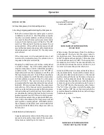
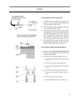
REMOVAL (ALL VSG 301-701 MODELS)
The removal of the gate rotor assembly for the VSG
301-701 compressors is similar for the VSG 901-
2101 compressors. The inner races are secured to
the stationary bearing spindle.
A) Prepare the compressor for servicing.
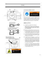
B) Remove the upper bolt from the side cover and
install a guide stud in the hole. Remove the
remaining bolts and side cover. There will be
some oil drainage when the cover is removed.
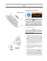
C) The side cover that contains the suction strainer
should have the suction line properly supported
before the bolts securing the line to the cover
can be removed. After the line is removed, the
cover can be removed per paragraph B.
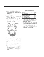
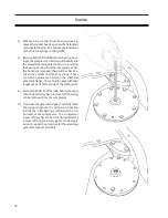
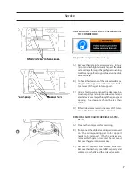
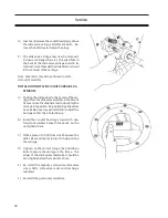
D) Turn the main rotor so the driving edge of the
groove is between the top of the shelf or slightly
below the back of the gate rotor support. At
this point install the gate rotor stabilizing tool.
Service
Summary of Contents for VSG
Page 2: ...2 ...
Page 4: ...4 ...
Page 56: ...56 ...
Page 58: ...58 Gate Rotor ...
Page 64: ...64 Main Rotor ...
Page 66: ...66 Slide Valve Cross Shafts and End Plate ...
Page 68: ...68 Capacity Slide Volume Slide Carriage Assembly Slide Valve Carriage Assembly ...
Page 72: ...72 Actuator Command Shaft ...
Page 74: ...74 VSG Screw Compressor Miscellaneous Frame Components ...
Page 78: ...78 Replacement Tools 291 1551 ...
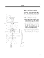
Page 82: ...82 Gaterotor Assembly ...
Page 86: ...86 Main Rotor Slide Valve Cross Shafts End Plate Models VSG301 401 Counter Clockwise ONLY ...
Page 88: ...88 Main Rotor Slide Valve Cross Shafts End Plate Models VSG501 701 Clockwise ONLY ...
Page 92: ...92 Actuator Command Shaft ...
Page 94: ...94 Model VSG 501 701 Model VSG 301 401 Miscellaneous Frame Components ...
Page 96: ...96 Housing Accessories Miscellaneous Frame Components ...
Page 99: ...99 ...


