


18
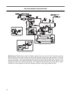
3. If not already done, mount the slide valve actua-
tor per (“Vilter Actuator set up for Capacity and
Volume Slide Motors). Next, wire the actuator
per the attached wiring diagrams, using the
already installed electrical conduit to run the
cables. The old wiring can be used to pull the
new cables through the conduit to the con-
trol panel. The cables may also be externally
tie-wrapped to the conduit
. Run the yellow
AC power cable(s) and the gray DC position
transmitter cable(s) in different conduit.
This
prevents the DC position transmitter cable from
picking up electrical noise from the AC power
cable.
Do not connect either of the cables to
the actuators yet.
In addition, if the actuators are replacing old gear-
motors on early units,
you must remove the capaci-
tors and associated wiring from inside the control
panel.
This is necessary to prevent electrical damage
to the new actuator motor.
4. When completing the calibration of the new
actuators, the motors are signaled to move
to below 5%. This may not completely occur
when exiting the calibration screen due to a
“program timer”. HOWEVER, when the com-
pressor actually starts, the motors will travel
below 5% and function correctly. The user may
see that the actuators are not below 5% after
calibration and try to find the reason. If the
calibration screen is re-entered right away and
then exited, the timer will allow the actuator
to go below the 5% on the screen. This may
be perceived as a problem; in reality,it is not.
5. Note:The 0 to 5V-position transmitter
output of the actuator will fluctuate wildly
during the calibration process. To prevent
damage to the actuators, do not connect the
yellow power cable or the gray position
transmitter cable until instructed to do so
later on.
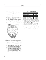
6. Open the plastic cover of the capacity motor by
removing the four #10 screws.
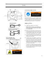
Installation & Calibration of Slide Valve Actuators
Slide Valve Actuator Installation Instructions
Caution
WHEN INSTALLING THE OPTICAL SLIDE MOTOR,
LOOSEN LOCKING COLLAR BEFORE SLIDING THE
COLLAR DOWN ON THE SHAFT. DO NOT USE A
SCREWDRIVER TO PRY LOCKING COLLAR INTO
POSITION.
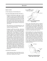
OVERVIEW
Calibration of an optical slide valve actuator is a two
step process that must be done for each actuator
installed of the compressor. Briefly, the steps are as
follows.
1) The actuator motor control module, located
inside the actuator housing, is calibrated so
that it knows the minimum and maximum ro-
tational positions of the slide valve it controls.
The calibrated actuator will output 0 VDC at the
minimum position and 5 VDC at the maximum
position.
2) After the actuator motor control module has been
calibrated for 0-5Volts, the controlling channel
corresponding to the actuator motor (either the
capacity or volume) has to be calibrated. This
instructs the control panel to learn the rotational
0% position & rotational 100% position of the slide
valve travel.
PLEASE NOTE:
Because there is an optical sensor on this motor, do
not attempt calibration in direct sunlight.
ACTUATOR MOTOR CONTROL
MODULE CALIBRATION PROCEDURE
1. Disable the Slide Non-Movement Alarm by go-
ing to the “Setup” menu on the control panel
and choosing “Alarm Disable” for the Slide Non-
Movement Option. (If applicable).
2. Completely shut off the power to the control
panel completely.
Summary of Contents for VSG
Page 2: ...2 ...
Page 4: ...4 ...
Page 56: ...56 ...
Page 58: ...58 Gate Rotor ...
Page 64: ...64 Main Rotor ...
Page 66: ...66 Slide Valve Cross Shafts and End Plate ...
Page 68: ...68 Capacity Slide Volume Slide Carriage Assembly Slide Valve Carriage Assembly ...
Page 72: ...72 Actuator Command Shaft ...
Page 74: ...74 VSG Screw Compressor Miscellaneous Frame Components ...
Page 78: ...78 Replacement Tools 291 1551 ...
Page 82: ...82 Gaterotor Assembly ...
Page 86: ...86 Main Rotor Slide Valve Cross Shafts End Plate Models VSG301 401 Counter Clockwise ONLY ...
Page 88: ...88 Main Rotor Slide Valve Cross Shafts End Plate Models VSG501 701 Clockwise ONLY ...
Page 92: ...92 Actuator Command Shaft ...
Page 94: ...94 Model VSG 501 701 Model VSG 301 401 Miscellaneous Frame Components ...
Page 96: ...96 Housing Accessories Miscellaneous Frame Components ...
Page 99: ...99 ...


