2-8
F-459-R1
TIRES, BRAKES AND DRIVETRAIN
Hydraulic Brake Drums
NOTE
Whenever servicing and/or replacing a brake drum
assembly, you must service both sides of the truck to
prevent premature wear and uneven braking action. The
drum and the wheel are an integrated assembly.
Measure Brake Drum Diameter
Repeat steps 1 through 8 of preceding section
“Checking/Changing Brake Shoes”, beginning on
Check the drums for scoring, cracks, deep grooves, a
raised lip on the outer edge, signs of overheating, out of
round or other damage.
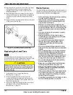
Drum diameter measurements may be checked with the
drum removed from the truck. Using a brake drum gauge,
measure the diameter at four or more points on the drum
and make sure all measurements are taken at the same
distance in from the outer edge of the drum. See
Figure 2-6.
Thickness variations of more then 0.005” (0.13 mm) can
cause pedal pulsation and/or vibration when applying the
brakes. A drum that does not meet these specifications
must be machined or replaced.
Figure 2-6 Typical Brake Drum Gauge
Replacing Brake Drum Assemblies
1.
Repeat Steps 1 through 9 of preceding section
“Checking/Changing Brake Shoes”, beginning on
2.
Check the brake lines for cracks, splits or any
apparent weaknesses. Replace as needed.
3.
Loosen the locknut and hardware from the spindle.
DO NOT remove nut from the assembly at this time.
4.
Rock the drum while gently pulling on the drum.
5.
If needed, using the rubber mallet (dead-blow
hammer), hit the drum on the opposite side, driving it
towards the loosened nut.
6.
Repeatedly hit the drum evenly in a circular motion
until it pops free, then remove the nut.
7.
Remove the drum and tire assembly.
NOTE
Brake drum/wheel assemblies are heavy. When handling
the new drum, protect the finish surfaces from damage.
Damage to the braking surfaces renders the brake drum
useless. The tire must be pressed on the new drum
before assembly.
8.
Install the new drum and tire assembly to the spindle,
being careful not to damage the grease seal during
assembly. Make sure the spindle is clean and free of
dirt and grease and then install.
9.
Carefully place the wheel onto the spindle and push
the outer grease-packed bearing into position.
10. Install the tanged lock washer, then install the spindle
nut and tighten to 22 (±2) ft. lbs., 30 (±3) Nm. to seat
the bearings.
11. Spin the wheel to make sure it turns free, then back
off the wheel nut 1/2 turn and re-tighten to the
specified torque. Again, check to make sure the
wheel turns freely.
12. Bend the tangs of the lock washer into the nearest
notches in the wheel nut. Back-off the nut slightly as
necessary to align it with the nearest lock washer
tangs.
13. Apply a thin layer of grease to the hub cap o-ring and
press hub cap into the hub.
Parking Brake Assembly
The parking brake is electronic and automatically locks
the rear drive wheel when the key is off or if the operator
is off the seat for 3 seconds or more.
Checking the Parking Brake
CAUTION
The parking brake system is controlled by the truck’s
control system.
The intention of this test is to have the drive
wheel lock up.
Do not do this test at high speeds!
Do this at a slow creep speed only with no load
on the forks.
https://www.forkliftpdfmanuals.com/

